DEMO9S08EL32 Freescale Semiconductor, DEMO9S08EL32 Datasheet - Page 200
DEMO9S08EL32
Manufacturer Part Number
DEMO9S08EL32
Description
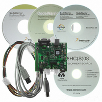
BOARD DEMO FOR 9S08 EL MCU
Manufacturer
Freescale Semiconductor
Type
MCUr
Datasheets
1.DEMO9S08EL32.pdf
(356 pages)
2.DEMO9S08EL32.pdf
(14 pages)
3.DEMO9S08EL32.pdf
(2 pages)
Specifications of DEMO9S08EL32
Contents
Evaluation Board
Processor To Be Evaluated
MC9S08EL32
Data Bus Width
8 bit
Interface Type
RS-232, USB
Operating Supply Voltage
12 V
Silicon Manufacturer
Freescale
Core Architecture
HCS08
Core Sub-architecture
HCS08
Silicon Core Number
MC9S08
Silicon Family Name
S08EL
Rohs Compliant
Yes
For Use With/related Products
MC9S08EL32
Lead Free Status / RoHS Status
Lead free / RoHS Compliant


12.3.6
The SLIC data length code register (SLCDLC) is the primary functional control register for the SLIC
module during normal LIN operations. It contains the data length code of the message buffer, indicating
how many bytes of data are to be sent or received, as well as the checksum mode control and transmit
enabling bit.
202
CHKMOD
TXGO
Field
DLC
5:0
7
6
Reset
W
R
SLIC Data Length Code Register (SLCDLC)
SLIC Transmit Go — This bit controls whether the SLIC module is sending or receiving data bytes. This bit is
automatically reset to 0 after a transmit operation is complete or an error is encountered and transmission has
been aborted.
0 SLIC receive data
1 Initiate SLIC transmit— The SLIC assumes the user has loaded the proper data into the message buffer and
LIN Checksum Mode — CHKMOD is used to decide what checksum method to use for this message frame.
Resets after error code or message frame complete. CHKMOD must be written (124 desired) only after the
reception of an identifier and before the reception or transmission of data bytes. Writing this bit to a one clears
the current checksum calculation.
0 Checksum calculated 119 the identifier byte included
1 Checksum calculated without the identifier byte (LIN spec <= 1.3)
Data Length Control Bits — The value of the bits indicate the number of data bytes in message. Values
0x00–0x07 are for “normal” LIN messaging. Values 0x08–0x3F are for “extended” LIN messaging. See
Table
TXGO
will begin transmitting the number of bytes indicated in the SLCDLC bits. If the number of bytes is greater than
8, the first 8 bytes will be transmitted and an interrupt will be triggered (if unmasked) for the user to enter the
next bytes of the message. If the number of bytes is 8 or fewer, the SLIC will transmit the appropriate number
of bytes and automatically append the checksum to the transmission. If IMSG or TXABRT are set or the SLCF
flag is set, writes to TXGO will have no effect.
(SAE J2602/LIN 2.0)
0
7
12-11.
MC9S08EL32 Series and MC9S08SL16 Series Data Sheet, Rev. 3
Figure 12-10. SLIC Data Length Code Register (SLCDLC)
CHKMOD
6
0
DLC[5:0]
0x3D
0x3E
0x00
0x01
0x02
0x3F
...
Table 12-10. SLCDLC Field Descriptions
Table 12-11. Data Length Control
DLC5
0
5
Message Data Length (Number of Bytes)
DLC4
4
0
Description
62
63
64
...
1
2
3
DLC3
0
3
DLC2
2
0
Freescale Semiconductor
DLC1
0
1
DLC0
0
0
Related parts for DEMO9S08EL32
Image
Part Number
Description
Manufacturer
Datasheet
Request
R

Part Number:
Description:
Manufacturer:
Freescale Semiconductor, Inc
Datasheet:
Part Number:
Description:
Manufacturer:
Freescale Semiconductor, Inc
Datasheet:
Part Number:
Description:
Manufacturer:
Freescale Semiconductor, Inc
Datasheet:
Part Number:
Description:
Manufacturer:
Freescale Semiconductor, Inc
Datasheet:
Part Number:
Description:
Manufacturer:
Freescale Semiconductor, Inc
Datasheet:
Part Number:
Description:
Manufacturer:
Freescale Semiconductor, Inc
Datasheet:
Part Number:
Description:
Manufacturer:
Freescale Semiconductor, Inc
Datasheet:
Part Number:
Description:
Manufacturer:
Freescale Semiconductor, Inc
Datasheet:
Part Number:
Description:
Manufacturer:
Freescale Semiconductor, Inc
Datasheet:
Part Number:
Description:
Manufacturer:
Freescale Semiconductor, Inc
Datasheet:
Part Number:
Description:
Manufacturer:
Freescale Semiconductor, Inc
Datasheet:
Part Number:
Description:
Manufacturer:
Freescale Semiconductor, Inc
Datasheet:
Part Number:
Description:
Manufacturer:
Freescale Semiconductor, Inc
Datasheet:
Part Number:
Description:
Manufacturer:
Freescale Semiconductor, Inc
Datasheet:
Part Number:
Description:
Manufacturer:
Freescale Semiconductor, Inc
Datasheet: