MC56F8122VFAE Freescale Semiconductor, MC56F8122VFAE Datasheet - Page 54
MC56F8122VFAE
Manufacturer Part Number
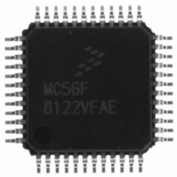
MC56F8122VFAE
Description
IC DSP 16BIT 40MHZ 48-LQFP
Manufacturer
Freescale Semiconductor
Series
56F8xxxr
Datasheet
1.MC56F8122VFAE.pdf
(136 pages)
Specifications of MC56F8122VFAE
Core Processor
56800
Core Size
16-Bit
Speed
40MHz
Connectivity
SCI, SPI
Peripherals
POR, WDT
Number Of I /o
21
Program Memory Size
32KB (16K x 16)
Program Memory Type
FLASH
Ram Size
4K x 16
Voltage - Supply (vcc/vdd)
2.25 V ~ 3.6 V
Data Converters
A/D 6x12b
Oscillator Type
Internal
Operating Temperature
-40°C ~ 105°C
Package / Case
48-LQFP
Data Bus Width
16 bit
Processor Series
MC56F81xx
Core
56800E
Maximum Clock Frequency
40 MHz
Number Of Programmable I/os
21
Data Ram Size
8 KB
Operating Supply Voltage
- 0.3 V to + 4 V
Maximum Operating Temperature
+ 105 C
Mounting Style
SMD/SMT
Data Rom Size
8 KB
Minimum Operating Temperature
- 40 C
Lead Free Status / RoHS Status
Lead free / RoHS Compliant
Eeprom Size
-
Lead Free Status / Rohs Status
Lead free / RoHS Compliant
Available stocks
Company
Part Number
Manufacturer
Quantity
Price
Company:

Part Number:
MC56F8122VFAE
Manufacturer:
Freescale Semiconductor
Quantity:
10 000


4.8 Factory-Programmed Memory
The Boot Flash memory block is programmed during manufacturing with a default Serial Bootloader
program. The Serial Bootloader application can be used to load a user application into the Program and
Data Flash (not available on the 56F8122) memories of the device. The 56F83xx SCI/CAN Bootloader
User Manual provides detailed information on this firmware. An application note, Production Flash
Programming, details how the Serial Bootloader program can be used to perform production Flash
programming of the on-board Flash memories as well as other optional methods.
Like all the Flash memory blocks, the Boot Flash can be erased and programmed by the user. The Serial
Bootloader application is programmed as an aid to the end user, but is not required to be used or maintained
in the Boot Flash memory.
Part 5 Interrupt Controller (ITCN)
5.1 Introduction
The Interrupt Controller (ITCN) module is used to arbitrate between various interrupt requests (IRQs), to
signal to the 56800E core when an interrupt of sufficient priority exists, and to what address to jump in
order to service this interrupt.
5.2 Features
The ITCN module design includes these distinctive features:
For further information, see
5.3 Functional Description
The Interrupt Controller is a slave on the IPBus. It contains registers allowing each of the 82 interrupt
sources to be set to one of four priority levels, excluding certain interrupts of fixed priority. Next, all of
the interrupt requests of a given level are priority encoded to determine the lowest numerical value of the
active interrupt requests for that level. Within a given priority level, 0 is the highest priority, while number
81 is the lowest.
5.3.1
Once the ITCN has determined that an interrupt is to be serviced and which interrupt has the highest
priority, an interrupt vector address is generated. Normal interrupt handling concatenates the VBA and the
vector number to determine the vector address. In this way, an offset is generated into the vector table for
each interrupt.
54
•
•
•
•
Programmable priority levels for each IRQ
Two programmable Fast Interrupts
Notification to SIM module to restart clocks out of Wait and Stop modes
Drives initial address on the address bus after reset
Normal Interrupt Handling
Table
4-3, Interrupt Vector Table Contents.
56F8322 Techncial Data, Rev. 16
Freescale Semiconductor
Preliminary
Related parts for MC56F8122VFAE
Image
Part Number
Description
Manufacturer
Datasheet
Request
R

Part Number:
Description:
Manufacturer:
Freescale Semiconductor, Inc
Datasheet:
Part Number:
Description:
Manufacturer:
Freescale Semiconductor, Inc
Datasheet:
Part Number:
Description:
Manufacturer:
Freescale Semiconductor, Inc
Datasheet:
Part Number:
Description:
Manufacturer:
Freescale Semiconductor, Inc
Datasheet:
Part Number:
Description:
Manufacturer:
Freescale Semiconductor, Inc
Datasheet:
Part Number:
Description:
Manufacturer:
Freescale Semiconductor, Inc
Datasheet:
Part Number:
Description:
Manufacturer:
Freescale Semiconductor, Inc
Datasheet:
Part Number:
Description:
Manufacturer:
Freescale Semiconductor, Inc
Datasheet:
Part Number:
Description:
Manufacturer:
Freescale Semiconductor, Inc
Datasheet:
Part Number:
Description:
Manufacturer:
Freescale Semiconductor, Inc
Datasheet:
Part Number:
Description:
Manufacturer:
Freescale Semiconductor, Inc
Datasheet:
Part Number:
Description:
Manufacturer:
Freescale Semiconductor, Inc
Datasheet:
Part Number:
Description:
Manufacturer:
Freescale Semiconductor, Inc
Datasheet:
Part Number:
Description:
Manufacturer:
Freescale Semiconductor, Inc
Datasheet:
Part Number:
Description:
Manufacturer:
Freescale Semiconductor, Inc
Datasheet: