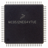
MC9S12NE64VTUE Freescale Semiconductor, MC9S12NE64VTUE Datasheet - Page 546

MC9S12NE64VTUE
Manufacturer Part Number
MC9S12NE64VTUE
Description
IC MCU 64K FLASH EEPROM 80-TQFP
Manufacturer
Freescale Semiconductor
Series
HCS12r
Datasheet
1.MC9S12NE64VTU.pdf
(554 pages)
Specifications of MC9S12NE64VTUE
Core Processor
HCS12
Core Size
16-Bit
Speed
25MHz
Connectivity
EBI/EMI, Ethernet, I²C, SCI, SPI
Peripherals
POR, PWM, WDT
Number Of I /o
38
Program Memory Size
64KB (64K x 8)
Program Memory Type
FLASH
Ram Size
8K x 8
Voltage - Supply (vcc/vdd)
2.375 V ~ 3.465 V
Data Converters
A/D 8x10b
Oscillator Type
Internal
Operating Temperature
-40°C ~ 105°C
Package / Case
80-TQFP Exposed Pad, 80-eTQFP, 80-HTQFP, 80-VQFP
Processor Series
S12N
Core
HCS12
Data Bus Width
16 bit
Data Ram Size
8 KB
Interface Type
I2C, SCI, SPI
Maximum Clock Frequency
125 MHz
Number Of Programmable I/os
70
Number Of Timers
4
Operating Supply Voltage
- 0.3 V to + 3 V
Maximum Operating Temperature
+ 105 C
Mounting Style
SMD/SMT
3rd Party Development Tools
EWHCS12
Development Tools By Supplier
EVB9S12NE64E, DEMO9S12NE64E
Minimum Operating Temperature
- 65 C
On-chip Adc
10 bit, 8 Channel
Cpu Family
HCS12
Device Core Size
16b
Frequency (max)
25MHz
Total Internal Ram Size
8KB
# I/os (max)
70
Number Of Timers - General Purpose
4
Operating Supply Voltage (typ)
2.5/3.3V
Operating Supply Voltage (max)
2.625/3.465V
Operating Supply Voltage (min)
2.357/2.375/3.135V
Instruction Set Architecture
CISC
Operating Temp Range
-40C to 105C
Operating Temperature Classification
Industrial
Mounting
Surface Mount
Pin Count
80
Package Type
TQFP
For Use With
EVB9S12NE64E - BOARD EVAL FOR 9S12NE64DEMO9S12NE64E - DEMO BOARD FOR 9S12NE64
Lead Free Status / RoHS Status
Lead free / RoHS Compliant
Eeprom Size
-
Lead Free Status / Rohs Status
Lead free / RoHS Compliant
Available stocks
Company
Part Number
Manufacturer
Quantity
Price
Company:
Part Number:
MC9S12NE64VTUE
Manufacturer:
Freescale Semiconductor
Quantity:
10 000
Part Number:
MC9S12NE64VTUE
Manufacturer:
FREESCALE
Quantity:
20 000
- Current page: 546 of 554
- Download datasheet (4Mb)
Appendix B Schematic and PCB Layout Design Recommendations
B.2
The section provides recommendations for general HCS12 PCB design and recommendations for PCB
design with Ethernet.
B.2.1
The PCB layout must be designed to ensure proper operation of the voltage regulator and the MCU. The
following recommendations are provided to ensure a robust PCB design:
B.2.2
When designing a PCB that uses the MC9S12NE64 Ethernet module, several design considerations must
be made to ensure that Ethernet operation conforms to the IEEE 802.3 physical interface specification.
These Ethernet PCB design recommendations include:
546
•
•
•
•
•
•
•
•
•
•
•
•
•
•
•
•
•
•
Every supply pair must be decoupled by a ceramic capacitor connected as near as possible to the
corresponding pins (C1 - C6).
Central point of the ground star should be the VSSX pin.
Use low ohmic low inductance connections between VSS1, VSS2 and VSSX.
VSSPLL must be directly connected to VSSX.
Keep traces of VSSPLL, EXTAL and XTAL as short as possible and occupied board area for
C7,C8, C11 and Q1 as small as possible.
Do not place other signals or supplies underneath area occupied by C7, C8, C10 and Q1 and the
connection area to the MCU.
Central power input should be fed in at the VDDA/VSSA pins.
The distance between the magnetic module and the RJ-45 jack is the most critical and must always
be as short as possible (less than one inch).
Never use 90° traces. Use 45° angles or radius curves in traces.
Trace widths of 0.010” are recommended. Wider is better. Trace widths should not vary.
Route differential Tx and Rx pairs near together (max 0.010” separation with 0.010” traces).
Trace lengths must always be as short as possible (must be less than one inch).
Make trace lengths as equal as possible.
Keep TX and RX differential pairs routes separated (at least 0.020” separation). Better to separate
with a ground plane.
Avoid routing Tx and Rx traces over or under a plane. Areas under the Tx and Rx traces should be
open.
Use precision components in the line termination circuitry with 1% tolerance.
Ensure that the power supply is rated for a load of 300 mA minimum.
Avoid vias and layer changes.
PCB Design Recommendation
General PCB Design Recommendations
Ethernet PCB Design Recommendations
MC9S12NE64 Data Sheet, Rev. 1.1
Freescale Semiconductor
Related parts for MC9S12NE64VTUE
Image
Part Number
Description
Manufacturer
Datasheet
Request
R
Part Number:
Description:
Manufacturer:
Freescale Semiconductor, Inc
Datasheet:
Part Number:
Description:
Manufacturer:
Freescale Semiconductor, Inc
Datasheet:
Part Number:
Description:
Manufacturer:
Freescale Semiconductor, Inc
Datasheet:
Part Number:
Description:
Manufacturer:
Freescale Semiconductor, Inc
Datasheet:
Part Number:
Description:
Manufacturer:
Freescale Semiconductor, Inc
Datasheet:
Part Number:
Description:
Manufacturer:
Freescale Semiconductor, Inc
Datasheet:
Part Number:
Description:
Manufacturer:
Freescale Semiconductor, Inc
Datasheet:
Part Number:
Description:
Manufacturer:
Freescale Semiconductor, Inc
Datasheet:
Part Number:
Description:
Manufacturer:
Freescale Semiconductor, Inc
Datasheet:
Part Number:
Description:
Manufacturer:
Freescale Semiconductor, Inc
Datasheet:
Part Number:
Description:
Manufacturer:
Freescale Semiconductor, Inc
Datasheet:
Part Number:
Description:
Manufacturer:
Freescale Semiconductor, Inc
Datasheet:
Part Number:
Description:
Manufacturer:
Freescale Semiconductor, Inc
Datasheet:
Part Number:
Description:
Manufacturer:
Freescale Semiconductor, Inc
Datasheet:
Part Number:
Description:
Manufacturer:
Freescale Semiconductor, Inc
Datasheet:


