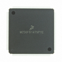
MC56F8147VPYE Freescale Semiconductor, MC56F8147VPYE Datasheet - Page 137

MC56F8147VPYE
Manufacturer Part Number
MC56F8147VPYE
Description
IC DSP 16BIT 40MHZ 160-LQFP
Manufacturer
Freescale Semiconductor
Series
56F8xxxr
Datasheet
1.MC56F8147VPYE.pdf
(172 pages)
Specifications of MC56F8147VPYE
Core Processor
56800
Core Size
16-Bit
Speed
40MHz
Connectivity
EBI/EMI, SCI, SPI
Peripherals
POR, PWM, WDT
Number Of I /o
76
Program Memory Size
128KB (64K x 16)
Program Memory Type
FLASH
Ram Size
4K x 16
Voltage - Supply (vcc/vdd)
2.25 V ~ 3.6 V
Data Converters
A/D 16x12b
Oscillator Type
External
Operating Temperature
-40°C ~ 105°C
Package / Case
160-LQFP
Data Bus Width
16 bit
Processor Series
MC56F81xx
Core
56800E
Data Ram Size
4 KB
Interface Type
SPI, SCI, CAN
Maximum Clock Frequency
40 MHz
Number Of Programmable I/os
76
Number Of Timers
2
Maximum Operating Temperature
+ 105 C
Mounting Style
SMD/SMT
Minimum Operating Temperature
- 40 C
On-chip Adc
4 x 12 bit, 4 Channel
Lead Free Status / RoHS Status
Lead free / RoHS Compliant
Eeprom Size
-
Lead Free Status / Rohs Status
Lead free / RoHS Compliant
Available stocks
Company
Part Number
Manufacturer
Quantity
Price
Company:
Part Number:
MC56F8147VPYE
Manufacturer:
FREESCAL
Quantity:
253
Company:
Part Number:
MC56F8147VPYE
Manufacturer:
Freescale Semiconductor
Quantity:
10 000
10.5 External Clock Operation Timing
10.6 Phase Locked Loop Timing
Freescale Semiconductor
Preliminary
1. An externally supplied reference clock should be as free as possible from any phase jitter for the PLL to work correctly.
2. ZCLK may not exceed 60MHz. For additional information on ZCLK and (f
3. This is the minimum time required after the PLL set up is changed to ensure reliable operation.
1. Parameters listed are guaranteed by design.
2. See
3. The high or low pulse width must be no smaller than 8.0ns or the chip will not function.
4. External clock input rise time is measured from 10% to 90%.
5. External clock input fall time is measured from 90% to 10%.
External reference crystal frequency for the PLL
PLL output frequency
PLL stabilization time
Frequency of operation (external clock driver)
Clock Pulse Width
External clock input rise time
External clock input fall time
The PLL is optimized for 8MHz input crystal.
the 56F8300 Peripheral User Manual.
External
Note: The midpoint is V
Clock
Figure 10-3
Table 10-13 External Clock Operation Timing Requirements
Characteristic
Characteristic
for details on using the recommended connection of an external clock driver.
3
10%
50%
90%
2
3
-40° to +125°C
(f
OUT
t
PW
IL
)
5
4
+ (V
Figure 10-3 External Clock Timing
IH
– V
IL
Table 10-14 PLL Timing
56F8347 Technical Data, Rev.11
)/2.
2
t
PW
1
Symbol
f
t
t
Symbol
t
osc
PW
rise
fall
f
t
f
osc
plls
op
Min
3.0
—
—
0
Min
OUT
160
t
—
fall
4
/2), please refer to the OCCS chapter in
Typ
—
—
—
—
Typ
—
8
1
External Clock Operation Timing
t
rise
Max
Max
120
260
8.4
10
10
—
10
1
10%
50%
90%
MHz
V
V
Unit
MHz
MHz
Unit
ns
ns
ns
ms
IH
IL
137


