MCHC705JJ7CPE Freescale Semiconductor, MCHC705JJ7CPE Datasheet - Page 114
MCHC705JJ7CPE
Manufacturer Part Number
MCHC705JJ7CPE
Description
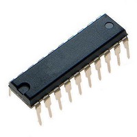
IC MCU 8BIT 224 BYTES RAM 20PDIP
Manufacturer
Freescale Semiconductor
Series
HC05r
Datasheet
1.MC705JJ7CDWE.pdf
(164 pages)
Specifications of MCHC705JJ7CPE
Core Processor
HC05
Core Size
8-Bit
Speed
2.1MHz
Connectivity
SIO
Peripherals
POR, Temp Sensor, WDT
Number Of I /o
14
Program Memory Size
6KB (6K x 8)
Program Memory Type
OTP
Ram Size
224 x 8
Voltage - Supply (vcc/vdd)
2.7 V ~ 5.5 V
Data Converters
A/D 4x12b
Oscillator Type
Internal
Operating Temperature
-40°C ~ 85°C
Package / Case
20-DIP (0.300", 7.62mm)
Processor Series
HC705JJ
Core
HC05
Data Bus Width
8 bit
Data Ram Size
224 B
Interface Type
SIOP
Maximum Clock Frequency
2.1 MHz
Number Of Programmable I/os
14
Number Of Timers
2
Maximum Operating Temperature
+ 85 C
Mounting Style
Through Hole
Minimum Operating Temperature
- 40 C
On-chip Adc
12 bit, 4 Channel
Package
20PDIP
Family Name
HC05
Maximum Speed
2.1 MHz
Operating Supply Voltage
3.3|5 V
Lead Free Status / RoHS Status
Lead free / RoHS Compliant
Eeprom Size
-
Lead Free Status / Rohs Status
Details


Programmable Timer
TOF — Timer Overflow Flag
11.8 Timer Operation during Wait Mode
During wait mode, the 16-bit timer continues to operate normally and may generate an interrupt to trigger
the MCU out of wait mode.
11.9 Timer Operation during Stop Mode
When the MCU enters stop mode, the free-running counter stops counting (the internal processor clock
is stopped). It remains at that particular count value until stop mode is exited by applying a low signal to
the IRQ/V
If stop mode is exited via an external reset (logic low applied to the RESET pin), the counter is forced to
$FFFC.
If a valid input capture edge occurs during stop mode, the input capture detect circuitry will be armed. This
action does not set any flags or wake up the MCU, but when the MCU does wake up there will be an active
input capture flag (and data) from the first valid edge. If the stop mode is exited by an external reset, no
input capture flag or data will be present even if a valid input capture edge was detected during stop mode.
11.10 Timer Operation during Halt Mode
When the MCU enters halt mode, the functions and states of the 16-bit programmable timer are the same
as for wait mode described in
114
The TOF bit is automatically set when the 16-bit timer counter rolls over from $FFFF to $0000. Clear
the TOF bit by reading the timer status register with the TOF set and then accessing the low byte
(TMRL, $0019) of the timer registers. Resets have no effect on TOF.
PP
pin, at which time the counter resumes from its stopped value as if nothing had happened.
MC68HC705JJ7 • MC68HC705JP7 Advance Information Data Sheet, Rev. 4.1
11.8 Timer Operation during Wait
Mode.
Freescale Semiconductor
Related parts for MCHC705JJ7CPE
Image
Part Number
Description
Manufacturer
Datasheet
Request
R

Part Number:
Description:
Manufacturer:
Freescale Semiconductor, Inc
Datasheet:
Part Number:
Description:
Manufacturer:
Freescale Semiconductor, Inc
Datasheet:
Part Number:
Description:
Manufacturer:
Freescale Semiconductor, Inc
Datasheet:
Part Number:
Description:
Manufacturer:
Freescale Semiconductor, Inc
Datasheet:
Part Number:
Description:
Manufacturer:
Freescale Semiconductor, Inc
Datasheet:
Part Number:
Description:
Manufacturer:
Freescale Semiconductor, Inc
Datasheet:
Part Number:
Description:
Manufacturer:
Freescale Semiconductor, Inc
Datasheet:
Part Number:
Description:
Manufacturer:
Freescale Semiconductor, Inc
Datasheet:
Part Number:
Description:
Manufacturer:
Freescale Semiconductor, Inc
Datasheet:
Part Number:
Description:
Manufacturer:
Freescale Semiconductor, Inc
Datasheet:
Part Number:
Description:
Manufacturer:
Freescale Semiconductor, Inc
Datasheet:
Part Number:
Description:
Manufacturer:
Freescale Semiconductor, Inc
Datasheet:
Part Number:
Description:
Manufacturer:
Freescale Semiconductor, Inc
Datasheet:
Part Number:
Description:
Manufacturer:
Freescale Semiconductor, Inc
Datasheet:
Part Number:
Description:
Manufacturer:
Freescale Semiconductor, Inc
Datasheet: