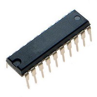
MCHC705JJ7CPE Freescale Semiconductor, MCHC705JJ7CPE Datasheet - Page 123

MCHC705JJ7CPE
Manufacturer Part Number
MCHC705JJ7CPE
Description
IC MCU 8BIT 224 BYTES RAM 20PDIP
Manufacturer
Freescale Semiconductor
Series
HC05r
Datasheet
1.MC705JJ7CDWE.pdf
(164 pages)
Specifications of MCHC705JJ7CPE
Core Processor
HC05
Core Size
8-Bit
Speed
2.1MHz
Connectivity
SIO
Peripherals
POR, Temp Sensor, WDT
Number Of I /o
14
Program Memory Size
6KB (6K x 8)
Program Memory Type
OTP
Ram Size
224 x 8
Voltage - Supply (vcc/vdd)
2.7 V ~ 5.5 V
Data Converters
A/D 4x12b
Oscillator Type
Internal
Operating Temperature
-40°C ~ 85°C
Package / Case
20-DIP (0.300", 7.62mm)
Processor Series
HC705JJ
Core
HC05
Data Bus Width
8 bit
Data Ram Size
224 B
Interface Type
SIOP
Maximum Clock Frequency
2.1 MHz
Number Of Programmable I/os
14
Number Of Timers
2
Maximum Operating Temperature
+ 85 C
Mounting Style
Through Hole
Minimum Operating Temperature
- 40 C
On-chip Adc
12 bit, 4 Channel
Package
20PDIP
Family Name
HC05
Maximum Speed
2.1 MHz
Operating Supply Voltage
3.3|5 V
Lead Free Status / RoHS Status
Lead free / RoHS Compliant
Eeprom Size
-
Lead Free Status / Rohs Status
Details
13.3.1 MOR Programming
The contents of the MOR should be programmed using the programmer board. To program any bits in
the MOR, the desired bit states must be written to the MOR address and then the MPGM bit in the EPROG
register must be used. The following sequence will program the MOR:
Once the MOR bits have been programmed, some of the options may experience glitches in operation
after removal of the programming voltage. It is recommended that the part be reset before trying to verify
the contents of the user EPROM or the MOR itself.
13.3.2 EPMSEC Programming
The EPMSEC bit is programmable. To program the EPMSEC bit, the desired state must be written to the
COP address and then the MPGM bit in the EPROG register must be used. The following sequence will
program the EPMSEC bit:
Once the EPMSEC bit has been programmed to a logic 1, access to the contents of the EPROM and MOR
in the expanded non-user modes will be denied. It is therefore recommended that the user EPROM and
MOR in the part first be programmed and fully verified before setting the EPMSEC bit.
13.4 EPROM Erasing
MCUs with windowed packages permit EPROM erasing with ultraviolet light. Erase the EPROM by
exposing it to 15 Ws/cm
light source 1 inch from the window. Do not use a shortwave filter. The erased state of an EPROM bit is
a logic 0.
Freescale Semiconductor
1. Write the desired data to the MOR location ($1FF1).
2. Apply the programming voltage to the IRQ/V
3. Set the MPGM bit in the EPROG.
4. Wait for the programming time, t
5. Clear the MPGM bit in the EPROG.
6. Remove the programming voltage from the IRQ/V
1. Write the desired data to bit 7 of the COPR location ($1FF0).
2. Apply the programming voltage to the IRQ/V
3. Set the MPGM bit in the EPROG.
4. Wait for the programming time, t
5. Clear the MPGM bit in the EPROG.
6. Remove the programming voltage from the IRQ/V
The contents of the EPROM or the MOR cannot be accessed if the
EPMSEC bit in the COPR register has been set.
Unlike many commercial EPROMs, an erased EPROM byte in the MCU will
read as $00. All unused locations should be programmed as 0s.
MC68HC705JJ7 • MC68HC705JP7 Advance Information Data Sheet, Rev. 4.1
2
of ultraviolet light with a wavelength of 2537 angstroms. Position the ultraviolet
MPGM
MPGM
.
.
NOTE
NOTE
PP
PP
pin.
pin.
PP
PP
pin.
pin.
EPROM Erasing
123


