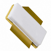
BLF6G10LS-135R,112 NXP Semiconductors, BLF6G10LS-135R,112 Datasheet - Page 78

BLF6G10LS-135R,112
Manufacturer Part Number
BLF6G10LS-135R,112
Description
IC BASESTATION FINAL SOT502B
Manufacturer
NXP Semiconductors
Datasheets
1.BLF6G20LS-140118.pdf
(100 pages)
2.BLF6G20LS-140112.pdf
(110 pages)
3.BLF6G10LS-135R112.pdf
(10 pages)
Specifications of BLF6G10LS-135R,112
Package / Case
SOT502B
Transistor Type
LDMOS
Frequency
871.5MHz
Gain
21dB
Voltage - Rated
65V
Current Rating
32A
Current - Test
950mA
Voltage - Test
28V
Power - Output
26.5W
Configuration
Single
Transistor Polarity
N-Channel
Resistance Drain-source Rds (on)
0.1 Ohms
Drain-source Breakdown Voltage
65 V
Gate-source Breakdown Voltage
13 V
Continuous Drain Current
32 A
Maximum Operating Temperature
+ 225 C
Mounting Style
SMD/SMT
Minimum Operating Temperature
- 65 C
Channel Type
N
Channel Mode
Enhancement
Drain Source Voltage (max)
65V
Output Power (max)
26.5W(Typ)
Power Gain (typ)@vds
21@28VdB
Frequency (min)
869MHz
Frequency (max)
894MHz
Package Type
LDMOST
Pin Count
3
Forward Transconductance (typ)
13S
Drain Source Resistance (max)
100(Typ)@6.15Vmohm
Reverse Capacitance (typ)
2@28VpF
Operating Temp Range
-65C to 225C
Drain Efficiency (typ)
28%
Mounting
Surface Mount
Mode Of Operation
2-Carrier W-CDMA
Number Of Elements
1
Vswr (max)
10
Screening Level
Military
Lead Free Status / RoHS Status
Lead free / RoHS Compliant
Noise Figure
-
Lead Free Status / Rohs Status
Compliant
Other names
934061247112
BLF6G10LS-135R
BLF6G10LS-135R
BLF6G10LS-135R
BLF6G10LS-135R
3.7
3.7.1 Base Station transistors
http://www.nxp.com/products/mosfets/rf_power_transistors_ldmos/basestations/index.html#preview
Device naming conventions RF power base stations transistors
Why choose NXP Semiconductors‘ RF power transistors for base stations:
` Leading technology (generation 6 and 7 of LDMOS)
` Highest (system) efficiency
` Best ruggedness
` Advanced Doherty amplifier designs
` Industry’s first 3.8 GHz Doherty
` Industry’s first fully integrated Doherty amplifier
NXP offers complete line-ups of RF power transistors operation from 800 MHz right up to 3.8 GHz for base stations,
covering all cellular technologies (MC-GSM/EDGE, TDMA, (TD-S)CDMA, W-CDMA/UMTS) and WiMAX infrastructures.
3.7.1.1
80
B: semiconductor die made of Si
B: semiconductor die made of Si
driver
driver
driver
driver
driver
final
final
final
final
final
B L F 6 G
B L F 6 G
Function
NEW : RF power transistor selection guide on www.nxp.com/rfpower
L: high frequency power transistor
L: high frequency power transistor
F: LDMOS transistor in ceramic package
C: LDMOS transistor in air cavity plastic (ACP) package
D: fully integrated Doherty amplifier
M: MMIC module
F: LDMOS transistor in ceramic package
C: LDMOS transistor in air cavity plastic (ACP) package
D: fully integrated Doherty amplifier
M: MMIC module
LDMOS technology generation
LDMOS technology generation
G: standard LDMOS
G: standard LDMOS
NXP Semiconductors RF Manual 14
Easy-to-use parametric filters help you to choose the right RF
power transistor for your design.
RF power transistors
operating frequency (in 100MHz; maximum)
operating frequency (in 100MHz; maximum)
0.7 - 1.0 GHz line-up
22 L S
22 L S
BLF6G21-10G
BLM6G10-30
BLM6G10-30G
BLF6G10(S)-45
BLF6G10L(S)-40BRN
BLF6G10(LS)-135RN
BLF6G10(LS)-160RN
BLF6G10(LS)-200RN
BLF6G10L(S)-260PRN
BLF6G07L(S)-260PBM
option: low thermal resistivity
option: low thermal resistivity
option: earless package
option: earless package
P1dB power
P1dB power
-45 P R B N G
-45 P R B N G
Type
push-pull device
push-pull device
enhanced ruggedness
enhanced ruggedness
option: current sense lead
option: current sense lead
specialty
specialty
gullwing-shaped leads
gullwing-shaped leads
SOT1112A3/B3
SOT1110A3/B3
SOT539A3/B3
SOT834-1
SOT822-1
SOT538A
Package
SOT608
SOT502
SOT502
SOT502
th
edition
700 - 1000
700 - 1000
700 - 1000
700 - 1000
700 - 1000
688 - 1000
10 - 2200
728 - 960
728 - 960
728 - 810
MHz
f
range
P
26.5
0.7
2.5
W
32
40
40
60
L(AV)
2
2
1
28.5
11.5
11.5
η
7.8
15
15
28
27
27
31
%
D
18.5
22.5
22.5
dB
G
29
29
15
21
20
27
21
p
@V
22
28
28
28
28
23
28
32
28
28
V
DS


