MPC8379E-RDBA Freescale Semiconductor, MPC8379E-RDBA Datasheet - Page 105
MPC8379E-RDBA
Manufacturer Part Number
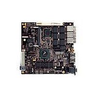
MPC8379E-RDBA
Description
BOARD REF DESIGN MPC8379E
Manufacturer
Freescale Semiconductor
Series
PowerQUICC II™ PROr
Type
MPUr
Specifications of MPC8379E-RDBA
Contents
Board
Memory Type
Flash, SDRAM
Interface Type
Ethernet, USB, PCI, UART
Board Size
170 mm x 170 mm
Product
Modules
Silicon Manufacturer
Freescale
Core Architecture
Power Architecture
Core Sub-architecture
PowerQUICC
Silicon Core Number
MPC83xx
Silicon Family Name
PowerQUICC II PRO
Rohs Compliant
Yes
For Use With/related Products
MPC8379E
Lead Free Status / RoHS Status
Lead free / RoHS Compliant


The junction to ambient thermal resistance is an industry-standard value that provides a quick and easy
estimation of thermal performance. Generally, the value obtained on a single layer board is appropriate for
a tightly packed printed circuit board. The value obtained on the board with the internal planes is usually
appropriate if the board has low power dissipation and the components are well separated. Test cases have
demonstrated that errors of a factor of two (in the quantity T
23.2.2
The thermal performance of a device cannot be adequately predicted from the junction to ambient thermal
resistance. The thermal performance of any component is strongly dependent on the power dissipation of
surrounding components. In addition, the ambient temperature varies widely within the application. For
many natural convection and especially closed box applications, the board temperature at the perimeter
(edge) of the package is approximately the same as the local air temperature near the device. Specifying
the local ambient conditions explicitly as the board temperature provides a more precise description of the
local ambient conditions that determine the temperature of the device.
At a known board temperature, the junction temperature is estimated using the following equation:
When the heat loss from the package case to the air can be ignored, acceptable predictions of junction
temperature can be made. The application board should be similar to the thermal test condition: the
component is soldered to a board with internal planes.
23.2.3
To determine the junction temperature of the device in the application after prototypes are available, use
the thermal characterization parameter (
temperature at the top center of the package case using the following equation:
Freescale Semiconductor
Estimation of Junction Temperature with Junction-to-Board
Thermal Resistance
Experimental Determination of Junction Temperature
The heat sink cannot be mounted on the package.
The heat sink cannot be mounted on the package.
T
where:
T
where:
MPC8379E PowerQUICC II Pro Processor Hardware Specifications, Rev. 4
J
J
= T
= T
P
T
R
P
T
T
A
T
A
J
T
D
θ
D
+ (R
+ (
JB
= junction temperature (°C)
= ambient temperature for the package (°C)
= thermocouple temperature on top of package (°C)
= power dissipation in the package (W)
= power dissipation in the package (W)
Ψ
= junction to board thermal resistance (°C/W) per JESD51-8
θ
JT
JB
× P
× P
D
D
)
)
Ψ
JT
) to determine the junction temperature and a measure of the
NOTE
NOTE
J
–
T
A
) are possible.
Thermal
105
Related parts for MPC8379E-RDBA
Image
Part Number
Description
Manufacturer
Datasheet
Request
R

Part Number:
Description:
BOARD REFERENCE FOR MPC837
Manufacturer:
Freescale Semiconductor
Datasheet:
Part Number:
Description:
BOARD PROCESSOR FOR MDS S
Manufacturer:
Freescale Semiconductor
Datasheet:

Part Number:
Description:
Powerquicc Ii Pro Processor Hardware Specifications
Manufacturer:
Freescale Semiconductor, Inc
Datasheet:

Part Number:
Description:
BOARD REF DES MPC8377 REV 2.1
Manufacturer:
Freescale Semiconductor
Datasheet:
Part Number:
Description:
Manufacturer:
Freescale Semiconductor, Inc
Datasheet:
Part Number:
Description:
Manufacturer:
Freescale Semiconductor, Inc
Datasheet:
Part Number:
Description:
Manufacturer:
Freescale Semiconductor, Inc
Datasheet:
Part Number:
Description:
Manufacturer:
Freescale Semiconductor, Inc
Datasheet:
Part Number:
Description:
Manufacturer:
Freescale Semiconductor, Inc
Datasheet:
Part Number:
Description:
Manufacturer:
Freescale Semiconductor, Inc
Datasheet:
Part Number:
Description:
Manufacturer:
Freescale Semiconductor, Inc
Datasheet:
Part Number:
Description:
Manufacturer:
Freescale Semiconductor, Inc
Datasheet:
Part Number:
Description:
Manufacturer:
Freescale Semiconductor, Inc
Datasheet:
Part Number:
Description:
Manufacturer:
Freescale Semiconductor, Inc
Datasheet:
Part Number:
Description:
Manufacturer:
Freescale Semiconductor, Inc
Datasheet: