MPC8379E-RDBA Freescale Semiconductor, MPC8379E-RDBA Datasheet - Page 71
MPC8379E-RDBA
Manufacturer Part Number
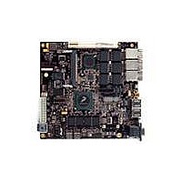
MPC8379E-RDBA
Description
BOARD REF DESIGN MPC8379E
Manufacturer
Freescale Semiconductor
Series
PowerQUICC II™ PROr
Type
MPUr
Specifications of MPC8379E-RDBA
Contents
Board
Memory Type
Flash, SDRAM
Interface Type
Ethernet, USB, PCI, UART
Board Size
170 mm x 170 mm
Product
Modules
Silicon Manufacturer
Freescale
Core Architecture
Power Architecture
Core Sub-architecture
PowerQUICC
Silicon Core Number
MPC83xx
Silicon Family Name
PowerQUICC II PRO
Rohs Compliant
Yes
For Use With/related Products
MPC8379E
Lead Free Status / RoHS Status
Lead free / RoHS Compliant


To illustrate these definitions using real values, consider the case of a CML (Current Mode Logic)
transmitter that has a common mode voltage of 2.25 V and each of its outputs, TD and TD, has a swing
that goes between 2.5 V and 2.0 V. Using these values, the peak-to-peak voltage swing of each signal (TD
or TD) is 500 mV
the differential signaling environment is fully symmetrical, the transmitter output’s differential swing
(V
between 500 mV and –500 mV, in other words, V
phase. The peak differential voltage (V
is 1000 mV
20.2
The SerDes reference clock inputs are applied to an internal PLL whose output creates the clock used by
the corresponding SerDes lanes. The SerDes reference clocks inputs are SD1_REF_CLK and
SD1_REF_CLK for both lanes of SerDes1, and SD2_REF_CLK and SD2_REF_CLK for both lanes of
SerDes2.
The following sections describe the SerDes reference clock requirements and some application
information.
20.2.1
Figure 49
Freescale Semiconductor
OD
•
) has the same amplitude as each signal’s single-ended swing. The differential output signal ranges
A Volts
B Volts
SerDes Reference Clock Receiver Reference Circuit Structure
— The SDn_REF_CLK and SDn_REF_CLK are internally AC-coupled differential inputs as
— The external reference clock driver must be able to drive this termination.
SerDes Reference Clocks
shows a receiver reference diagram of the SerDes reference clocks.
shown in
50 Ω termination to SGND_SRDSn (xcorevss) followed by on-chip AC-coupling.
p-p
SerDes Reference Clock Receiver Characteristics
.
p-p
Figure 48. Differential Voltage Definitions for Transmitter or Receiver
MPC8379E PowerQUICC II Pro Processor Hardware Specifications, Rev. 4
, which is referred as the single-ended swing for each signal. In this example, since
Figure
SDn_TX or
SDn_RX
SDn_TX or
SDn_RX
49. Each differential clock input (SDn_REF_CLK or SDn_REF_CLK) has a
Differential Peak-Peak Voltage, VDIFFpp = 2 × VDIFFp (not shown)
DIFFp
Differential Swing, VID or VOD = A – B
Differential Peak Voltage, VDIFFp = |A – B|
) is 500 mV. The peak-to-peak differential voltage (V
OD
is 500 mV in one phase and –500 mV in the other
High-Speed Serial Interfaces (HSSI)
V
cm
= (A + B)/2
DIFFp-p
71
)
Related parts for MPC8379E-RDBA
Image
Part Number
Description
Manufacturer
Datasheet
Request
R

Part Number:
Description:
BOARD REFERENCE FOR MPC837
Manufacturer:
Freescale Semiconductor
Datasheet:
Part Number:
Description:
BOARD PROCESSOR FOR MDS S
Manufacturer:
Freescale Semiconductor
Datasheet:

Part Number:
Description:
Powerquicc Ii Pro Processor Hardware Specifications
Manufacturer:
Freescale Semiconductor, Inc
Datasheet:

Part Number:
Description:
BOARD REF DES MPC8377 REV 2.1
Manufacturer:
Freescale Semiconductor
Datasheet:
Part Number:
Description:
Manufacturer:
Freescale Semiconductor, Inc
Datasheet:
Part Number:
Description:
Manufacturer:
Freescale Semiconductor, Inc
Datasheet:
Part Number:
Description:
Manufacturer:
Freescale Semiconductor, Inc
Datasheet:
Part Number:
Description:
Manufacturer:
Freescale Semiconductor, Inc
Datasheet:
Part Number:
Description:
Manufacturer:
Freescale Semiconductor, Inc
Datasheet:
Part Number:
Description:
Manufacturer:
Freescale Semiconductor, Inc
Datasheet:
Part Number:
Description:
Manufacturer:
Freescale Semiconductor, Inc
Datasheet:
Part Number:
Description:
Manufacturer:
Freescale Semiconductor, Inc
Datasheet:
Part Number:
Description:
Manufacturer:
Freescale Semiconductor, Inc
Datasheet:
Part Number:
Description:
Manufacturer:
Freescale Semiconductor, Inc
Datasheet:
Part Number:
Description:
Manufacturer:
Freescale Semiconductor, Inc
Datasheet: