MPC8379E-RDBA Freescale Semiconductor, MPC8379E-RDBA Datasheet - Page 73
MPC8379E-RDBA
Manufacturer Part Number
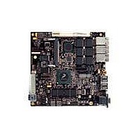
MPC8379E-RDBA
Description
BOARD REF DESIGN MPC8379E
Manufacturer
Freescale Semiconductor
Series
PowerQUICC II™ PROr
Type
MPUr
Specifications of MPC8379E-RDBA
Contents
Board
Memory Type
Flash, SDRAM
Interface Type
Ethernet, USB, PCI, UART
Board Size
170 mm x 170 mm
Product
Modules
Silicon Manufacturer
Freescale
Core Architecture
Power Architecture
Core Sub-architecture
PowerQUICC
Silicon Core Number
MPC83xx
Silicon Family Name
PowerQUICC II PRO
Rohs Compliant
Yes
For Use With/related Products
MPC8379E
Lead Free Status / RoHS Status
Lead free / RoHS Compliant


Freescale Semiconductor
•
SDn_REF_CLK
SDn_REF_CLK
— For external DC-coupled connection, as described in
— For external AC-coupled connection, there is no common mode voltage requirement for the
Single-ended Mode
— The reference clock can also be single-ended. The SD _REF_CLK input amplitude
— The SDn_REF_CLK input average voltage must be between 200 mV and 400 mV.
— To meet the input amplitude requirement, the reference clock inputs might need to be DC or
Figure 50. Differential Reference Clock Input DC Requirements (External DC-Coupled)
greater than 200 mV. This requirement is the same for both external DC-coupled or
AC-coupled connection.
Clock Receiver Characteristics,”
requirement for average voltage (common mode voltage) to be between 100 mV and 400 mV.
Figure 50
scheme.
clock driver. Since the external AC-coupling capacitor blocks the DC level, the clock driver
and the SerDes reference clock receiver operate in different command mode voltages. The
SerDes reference clock receiver in this connection scheme has its common mode voltage set to
SGND_SRDSn. Each signal wire of the differential inputs is allowed to swing below and above
the command mode voltage (SGND_SRDSn).
input requirement for AC-coupled connection scheme.
(single-ended swing) must be between 400 mV and 800 mV
SDn_REF_CLK either left unconnected or tied to ground.
shows the SerDes reference clock input requirement for single-ended signaling mode.
AC-coupled externally. For the best noise performance, the reference of the clock could be DC
or AC-coupled into the unused phase (SDn_REF_CLK) through the same source impedance as
the clock input (SDn_REF_CLK) in use.
MPC8379E PowerQUICC II Pro Processor Hardware Specifications, Rev. 4
shows the SerDes reference clock input requirement for DC-coupled connection
200 mV < Input Amplitude or Differential Peak < 800 mV
the maximum average current requirements sets the
Figure 51
Section 20.2.1, “SerDes Reference
shows the SerDes reference clock
p-p
(from V
High-Speed Serial Interfaces (HSSI)
100 mV < V
min
to V
V
max
cm
max
V
< 400 mV
< 800 mV
min
) with
Figure 52
> 0 V
73
Related parts for MPC8379E-RDBA
Image
Part Number
Description
Manufacturer
Datasheet
Request
R

Part Number:
Description:
BOARD REFERENCE FOR MPC837
Manufacturer:
Freescale Semiconductor
Datasheet:
Part Number:
Description:
BOARD PROCESSOR FOR MDS S
Manufacturer:
Freescale Semiconductor
Datasheet:

Part Number:
Description:
Powerquicc Ii Pro Processor Hardware Specifications
Manufacturer:
Freescale Semiconductor, Inc
Datasheet:

Part Number:
Description:
BOARD REF DES MPC8377 REV 2.1
Manufacturer:
Freescale Semiconductor
Datasheet:
Part Number:
Description:
Manufacturer:
Freescale Semiconductor, Inc
Datasheet:
Part Number:
Description:
Manufacturer:
Freescale Semiconductor, Inc
Datasheet:
Part Number:
Description:
Manufacturer:
Freescale Semiconductor, Inc
Datasheet:
Part Number:
Description:
Manufacturer:
Freescale Semiconductor, Inc
Datasheet:
Part Number:
Description:
Manufacturer:
Freescale Semiconductor, Inc
Datasheet:
Part Number:
Description:
Manufacturer:
Freescale Semiconductor, Inc
Datasheet:
Part Number:
Description:
Manufacturer:
Freescale Semiconductor, Inc
Datasheet:
Part Number:
Description:
Manufacturer:
Freescale Semiconductor, Inc
Datasheet:
Part Number:
Description:
Manufacturer:
Freescale Semiconductor, Inc
Datasheet:
Part Number:
Description:
Manufacturer:
Freescale Semiconductor, Inc
Datasheet:
Part Number:
Description:
Manufacturer:
Freescale Semiconductor, Inc
Datasheet: