MPC8379E-RDBA Freescale Semiconductor, MPC8379E-RDBA Datasheet - Page 106
MPC8379E-RDBA
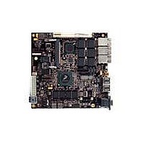
Manufacturer Part Number
MPC8379E-RDBA
Description
BOARD REF DESIGN MPC8379E
Manufacturer
Freescale Semiconductor
Series
PowerQUICC II™ PROr
Type
MPUr
Specifications of MPC8379E-RDBA
Contents
Board
Memory Type
Flash, SDRAM
Interface Type
Ethernet, USB, PCI, UART
Board Size
170 mm x 170 mm
Product
Modules
Silicon Manufacturer
Freescale
Core Architecture
Power Architecture
Core Sub-architecture
PowerQUICC
Silicon Core Number
MPC83xx
Silicon Family Name
PowerQUICC II PRO
Rohs Compliant
Yes
For Use With/related Products
MPC8379E
Lead Free Status / RoHS Status
Lead free / RoHS Compliant


Thermal
The thermal characterization parameter is measured per the JESD51-2 specification using a 40 gauge type
T thermocouple epoxied to the top center of the package case. The thermocouple should be positioned so
that the thermocouple junction rests on the package. A small amount of epoxy is placed over the
thermocouple junction and over about 1 mm of wire extending from the junction. The thermocouple wire
is placed flat against the package case to avoid measurement errors caused by cooling effects of the
thermocouple wire.
23.2.4
For the power values the device is expected to operate at, it is anticipated that a heat sink will be required.
A preliminary estimate of heat sink performance can be obtained from the following first first-cut
approach. The thermal resistance is expressed as the sum of a junction to case thermal resistance and a
case-to-ambient thermal resistance:
R
change the case to ambient thermal resistance, R
sink, the air flow around the device, the interface material, the mounting arrangement on printed circuit
board, or change the thermal dissipation on the printed circuit board surrounding the device.
This first-cut approach overestimates the heat sink size required, since heat flow through the board is not
accounted for, which can be as much as one-third to one-half of the power generated in the package.
Accurate thermal design requires thermal modeling of the application environment using computational
fluid dynamics software which can model both the conduction cooling through the package and board and
the convection cooling due to the air moving through the application. Simplified thermal models of the
packages can be assembled using the junction-to-case and junction-to-board thermal resistances listed in
the thermal resistance table. More detailed thermal models can be made available on request.
The thermal performance of devices with heat sinks has been simulated with a few commercially available
heat sinks. The heat sink choice is determined by the application environment (temperature, air flow,
adjacent component power dissipation) and the physical space available. Because of the wide variety of
application environments, a single standard heat sink applicable to all cannot be specified.
106
θ
JC
is device-related and cannot be influenced by the user. The user controls the thermal environment to
Heat Sinks and Junction-to-Case Thermal Resistance
R
where:
MPC8379E PowerQUICC II Pro Processor Hardware Specifications, Rev. 4
θ
JA
= R
Ψ
P
R
R
R
D
θ
θ
θ
JT
JA
JC
CA
θ
= power dissipation in the package (W)
JC
= junction to ambient thermal resistance (°C/W)
= junction to ambient thermal resistance (°C/W)
= junction to case thermal resistance (°C/W)
= case to ambient thermal resistance (°C/W)
+ R
θ
CA
θ
CA
. For instance, the user can change the size of the heat
Freescale Semiconductor
Related parts for MPC8379E-RDBA
Image
Part Number
Description
Manufacturer
Datasheet
Request
R

Part Number:
Description:
BOARD REFERENCE FOR MPC837
Manufacturer:
Freescale Semiconductor
Datasheet:
Part Number:
Description:
BOARD PROCESSOR FOR MDS S
Manufacturer:
Freescale Semiconductor
Datasheet:

Part Number:
Description:
Powerquicc Ii Pro Processor Hardware Specifications
Manufacturer:
Freescale Semiconductor, Inc
Datasheet:

Part Number:
Description:
BOARD REF DES MPC8377 REV 2.1
Manufacturer:
Freescale Semiconductor
Datasheet:
Part Number:
Description:
Manufacturer:
Freescale Semiconductor, Inc
Datasheet:
Part Number:
Description:
Manufacturer:
Freescale Semiconductor, Inc
Datasheet:
Part Number:
Description:
Manufacturer:
Freescale Semiconductor, Inc
Datasheet:
Part Number:
Description:
Manufacturer:
Freescale Semiconductor, Inc
Datasheet:
Part Number:
Description:
Manufacturer:
Freescale Semiconductor, Inc
Datasheet:
Part Number:
Description:
Manufacturer:
Freescale Semiconductor, Inc
Datasheet:
Part Number:
Description:
Manufacturer:
Freescale Semiconductor, Inc
Datasheet:
Part Number:
Description:
Manufacturer:
Freescale Semiconductor, Inc
Datasheet:
Part Number:
Description:
Manufacturer:
Freescale Semiconductor, Inc
Datasheet:
Part Number:
Description:
Manufacturer:
Freescale Semiconductor, Inc
Datasheet:
Part Number:
Description:
Manufacturer:
Freescale Semiconductor, Inc
Datasheet: