MPC8379E-RDBA Freescale Semiconductor, MPC8379E-RDBA Datasheet - Page 99
MPC8379E-RDBA
Manufacturer Part Number
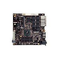
MPC8379E-RDBA
Description
BOARD REF DESIGN MPC8379E
Manufacturer
Freescale Semiconductor
Series
PowerQUICC II™ PROr
Type
MPUr
Specifications of MPC8379E-RDBA
Contents
Board
Memory Type
Flash, SDRAM
Interface Type
Ethernet, USB, PCI, UART
Board Size
170 mm x 170 mm
Product
Modules
Silicon Manufacturer
Freescale
Core Architecture
Power Architecture
Core Sub-architecture
PowerQUICC
Silicon Core Number
MPC83xx
Silicon Family Name
PowerQUICC II PRO
Rohs Compliant
Yes
For Use With/related Products
MPC8379E
Lead Free Status / RoHS Status
Lead free / RoHS Compliant


Table 71
conditions (see
22.1
The system PLL is controlled by the RCWLR[SPMF] parameter. The system PLL VCO frequency
depends on RCWLR[DDRCM] and RCWLR[LBCM].
for the system PLL.
Freescale Semiconductor
1
2
3
e300 core frequency (core_clk)
Coherent system bus frequency (csb_clk)
DDR2 memory bus frequency (MCK)
DDR1 memory bus frequency (MCK)
Local bus frequency (LCLKn)
Local bus controller frequency (lbc_clk)
PCI input frequency (CLKIN or PCI_CLK)
eTSEC frequency
Security encryption controller frequency
USB controller frequency
eSDHC controller frequency
SATA controller frequency
Note:
MCK, LCLK[0:2], and core_clk frequencies do not exceed their respective maximum or minimum operating frequencies. The
value of SCCR[xCM] must be programmed such that the maximum internal operating frequency of the Security core, USB
modules, SATA, and eSDHC will not exceed their respective value listed in this table.
csb_clk frequency (depending on RCWLR[LBCM]).
The CLKIN frequency, RCWLR[SPMF], and RCWLR[COREPLL] settings must be chosen such that the resulting csb_clk,
The DDR data rate is 2× the DDR memory bus frequency.
The local bus frequency is ½, ¼, or 1/8 of the lbiu_clk frequency (depending on LCRR[CLKDIV]) which is in turn 1× or 2× the
provides the operating frequencies for the TePBGA II package under recommended operating
System PLL Configuration
If RCWLR[DDRCM] and RCWLR[LBCM] are both cleared, the system
PLL VCO frequency = (CSB frequency) × (System PLL VCO Divider).
If either RCWLR[DDRCM] or RCWLR[LBCM] are set, the system PLL
VCO frequency = 2 × (CSB frequency) × (System PLL VCO Divider).
The VCO divider needs to be set properly so that the System PLL VCO
frequency is in the range of 400–800 MHz.
Table
MPC8379E PowerQUICC II Pro Processor Hardware Specifications, Rev. 4
3).
Parameter
3
Table 71. Operating Frequencies for TePBGA II
2
2
1
NOTE
Table 72
Minimum Operating
Frequency (MHz)
shows the multiplication factor encodings
333
133
125
167
25
—
—
—
—
—
—
—
Maximum Operating
Frequency (MHz)
800
400
200
333
133
400
400
200
200
200
200
66
Clocking
99
Related parts for MPC8379E-RDBA
Image
Part Number
Description
Manufacturer
Datasheet
Request
R

Part Number:
Description:
BOARD REFERENCE FOR MPC837
Manufacturer:
Freescale Semiconductor
Datasheet:
Part Number:
Description:
BOARD PROCESSOR FOR MDS S
Manufacturer:
Freescale Semiconductor
Datasheet:

Part Number:
Description:
Powerquicc Ii Pro Processor Hardware Specifications
Manufacturer:
Freescale Semiconductor, Inc
Datasheet:

Part Number:
Description:
BOARD REF DES MPC8377 REV 2.1
Manufacturer:
Freescale Semiconductor
Datasheet:
Part Number:
Description:
Manufacturer:
Freescale Semiconductor, Inc
Datasheet:
Part Number:
Description:
Manufacturer:
Freescale Semiconductor, Inc
Datasheet:
Part Number:
Description:
Manufacturer:
Freescale Semiconductor, Inc
Datasheet:
Part Number:
Description:
Manufacturer:
Freescale Semiconductor, Inc
Datasheet:
Part Number:
Description:
Manufacturer:
Freescale Semiconductor, Inc
Datasheet:
Part Number:
Description:
Manufacturer:
Freescale Semiconductor, Inc
Datasheet:
Part Number:
Description:
Manufacturer:
Freescale Semiconductor, Inc
Datasheet:
Part Number:
Description:
Manufacturer:
Freescale Semiconductor, Inc
Datasheet:
Part Number:
Description:
Manufacturer:
Freescale Semiconductor, Inc
Datasheet:
Part Number:
Description:
Manufacturer:
Freescale Semiconductor, Inc
Datasheet:
Part Number:
Description:
Manufacturer:
Freescale Semiconductor, Inc
Datasheet: