MPC8379E-RDBA Freescale Semiconductor, MPC8379E-RDBA Datasheet - Page 33
MPC8379E-RDBA
Manufacturer Part Number
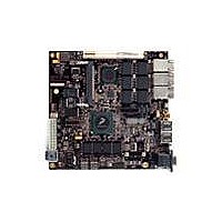
MPC8379E-RDBA
Description
BOARD REF DESIGN MPC8379E
Manufacturer
Freescale Semiconductor
Series
PowerQUICC II™ PROr
Type
MPUr
Specifications of MPC8379E-RDBA
Contents
Board
Memory Type
Flash, SDRAM
Interface Type
Ethernet, USB, PCI, UART
Board Size
170 mm x 170 mm
Product
Modules
Silicon Manufacturer
Freescale
Core Architecture
Power Architecture
Core Sub-architecture
PowerQUICC
Silicon Core Number
MPC83xx
Silicon Family Name
PowerQUICC II PRO
Rohs Compliant
Yes
For Use With/related Products
MPC8379E
Lead Free Status / RoHS Status
Lead free / RoHS Compliant


9.1
Table 34
OV
9.2
Table 35
Freescale Semiconductor
High-level input voltage
Low-level input voltage
Input current
High-level output voltage, I
Low-level output voltage, I
Note:
1
2
USB clock cycle time
Input setup to USB clock—all inputs
Input hold to USB clock—all inputs
USB clock to output valid—all outputs
Output hold from USB clock—all outputs
Note:
1
2
3
4
5
The minimum V
The symbol OV
The symbols for timing specifications follow the pattern of t
and t
the input (I) to go invalid (X) with respect to the time the USB clock reference (K) goes high (H). Also, t
USB timing (US) for the USB clock reference (K) to go high (H) with respect to the output (O) going invalid (X) or output hold
time.
All timings are in reference to the USB clock, USBDR_CLK.
All signals are measured from OV
signaling levels.
Input timings are measured at the pin.
For active/float timing measurements, the high impedance or off state is defined to be when the total current delivered through
the component pin is less than or equal to that of the leakage current specification.
DD
(First two letters of functional block)(reference)(state)(signal)(state)
= 3.3 V ± 165 mV.
provides the DC electrical characteristics for the ULPI interface at recommended
describes the general timing parameters of the USB interface of the device.
USB DC Electrical Characteristics
USB AC Electrical Specifications
IN
IL
Parameter
and maximum V
represents the input voltage of the supply and is referenced in
Parameter
MPC8379E PowerQUICC II Pro Processor Hardware Specifications, Rev. 4
OL
OH
Table 35. USB General Timing Parameters (ULPI Mode Only)
= 100 μA
= –100 μA
IH
DD
Table 34. USB DC Electrical Characteristics
values are based on the respective minimum and maximum OV
/2 of the rising edge of the USB clock to 0.4 × OV
Symbol
V
V
V
V
I
OH
IN
OL
IH
IL
Symbol
t
t
t
t
USKHOV
USKHOX
(First two letters of functional block)(signal)(state) (reference)(state)
for outputs. For example, t
USIVKH
USIXKH
t
USCK
OV
1
DD
–0.3
Min
—
—
2
– 0.2
Min
15
—
4
1
2
Table
OV
USIXKH
DD
Max
±30
DD
0.8
0.2
—
3.
+ 0.3
of the signal in question for 3.3-V
Max
—
—
—
—
7
symbolizes USB timing (US) for
IN
values found in
Unit
μA
USKHOX
V
V
V
V
Unit
ns
ns
ns
ns
ns
symbolizes
for inputs
2, 3, 4, 5
2, 3, 4, 5
2, 3, 4, 5
2, 3, 4, 5
2, 3, 4, 5
Notes
Notes
Table
—
—
1
1
2
USB
33
3.
Related parts for MPC8379E-RDBA
Image
Part Number
Description
Manufacturer
Datasheet
Request
R

Part Number:
Description:
BOARD REFERENCE FOR MPC837
Manufacturer:
Freescale Semiconductor
Datasheet:
Part Number:
Description:
BOARD PROCESSOR FOR MDS S
Manufacturer:
Freescale Semiconductor
Datasheet:

Part Number:
Description:
Powerquicc Ii Pro Processor Hardware Specifications
Manufacturer:
Freescale Semiconductor, Inc
Datasheet:

Part Number:
Description:
BOARD REF DES MPC8377 REV 2.1
Manufacturer:
Freescale Semiconductor
Datasheet:
Part Number:
Description:
Manufacturer:
Freescale Semiconductor, Inc
Datasheet:
Part Number:
Description:
Manufacturer:
Freescale Semiconductor, Inc
Datasheet:
Part Number:
Description:
Manufacturer:
Freescale Semiconductor, Inc
Datasheet:
Part Number:
Description:
Manufacturer:
Freescale Semiconductor, Inc
Datasheet:
Part Number:
Description:
Manufacturer:
Freescale Semiconductor, Inc
Datasheet:
Part Number:
Description:
Manufacturer:
Freescale Semiconductor, Inc
Datasheet:
Part Number:
Description:
Manufacturer:
Freescale Semiconductor, Inc
Datasheet:
Part Number:
Description:
Manufacturer:
Freescale Semiconductor, Inc
Datasheet:
Part Number:
Description:
Manufacturer:
Freescale Semiconductor, Inc
Datasheet:
Part Number:
Description:
Manufacturer:
Freescale Semiconductor, Inc
Datasheet:
Part Number:
Description:
Manufacturer:
Freescale Semiconductor, Inc
Datasheet: