DK-DEV-1AGX60N Altera, DK-DEV-1AGX60N Datasheet - Page 19
DK-DEV-1AGX60N
Manufacturer Part Number
DK-DEV-1AGX60N
Description
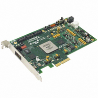
KIT DEV ARRIA GX 1AGX60N
Manufacturer
Altera
Series
Arria GXr
Type
FPGAr
Datasheet
1.EP1AGX20CF484C6N.pdf
(234 pages)
Specifications of DK-DEV-1AGX60N
Contents
Dev. Board, Quartus® II Web Edition, Reference Designs, Labs, and Complete Documentation
For Use With/related Products
1AGX60N
Lead Free Status / RoHS Status
Lead free / RoHS Compliant
Other names
544-2372
Available stocks
Company
Part Number
Manufacturer
Quantity
Price


Chapter 2: Arria GX Architecture
Transceivers
© December 2009 Altera Corporation
f
■
■
■
The CRU controls whether the receiver PLL locks to the input reference clock
(lock-to-reference mode) or the incoming serial data (lock-to data mode). You can set
the CRU to switch between lock-to-data and lock-to-reference modes automatically or
manually. In automatic lock mode, the phase detector and dedicated parts per million
(PPM) detector within each receiver channel control the switch between lock-to-data
and lock-to-reference modes based on some pre-set conditions. In manual lock mode,
you can control the switch manually using the rx_locktorefclk and
rx_locktodata signals.
For more information, refer to the “Clock Recovery Unit” section in the
Transceiver Protocol Support and Additional Features
Table 2–4
and rx_locktodata signals.
Table 2–4. CRU Manual Lock Signals
If the rx_locktorefclk and rx_locktodata ports are not used, the default
setting is automatic lock mode.
Deserializer
The deserializer block clocks in serial input data from the receiver buffer using the
high-speed serial recovered clock and deserializes into 8- or 10-bit parallel data using
the low-speed parallel recovered clock. The serial data is assumed to be received with
LSB first, followed by MSB. It feeds the deserialized 8- or 10-bit data to the word
aligner, as shown in
The voltage-controlled oscillator (V
Programmable frequency multiplication W of 1, 4, 5, 8, 10, 16, 20, and 25. Not all
settings are supported for any particular frequency.
Two lock indication signals are provided. They are found in PFD mode
(lock-to-reference clock), and PD (lock-to-data).
rx_locktorefclk
lists the behavior of the CRU block with respect to the rx_locktorefclk
1
0
x
Figure
2–14.
rx_locktodata
0
1
0
CO
) operates at half rate.
chapter.
Lock-to-reference clock
Lock-to-data
Automatic
Arria GX Device Handbook, Volume 1
CRU Mode
Arria GX
2–13
Related parts for DK-DEV-1AGX60N
Image
Part Number
Description
Manufacturer
Datasheet
Request
R

Part Number:
Description:
KIT DEV ARRIA II GX FPGA 2AGX125
Manufacturer:
Altera
Datasheet:

Part Number:
Description:
KIT DEV CYCLONE III LS EP3CLS200
Manufacturer:
Altera
Datasheet:

Part Number:
Description:
KIT DEV STRATIX IV FPGA 4SE530
Manufacturer:
Altera
Datasheet:

Part Number:
Description:
KIT DEV FPGA 2AGX260 W/6.375G TX
Manufacturer:
Altera
Datasheet:

Part Number:
Description:
KIT DEV MAX V 5M570Z
Manufacturer:
Altera
Datasheet:

Part Number:
Description:
KIT DEV STRATIX V FPGA 5SGXEA7
Manufacturer:
Altera
Datasheet:

Part Number:
Description:
KIT DEVELOPMENT STRATIX III
Manufacturer:
Altera
Datasheet:

Part Number:
Description:
KIT DEVELOPMENT STRATIX IV
Manufacturer:
Altera
Datasheet:
Part Number:
Description:
KIT STARTER CYCLONE IV GX
Manufacturer:
Altera
Datasheet:
Part Number:
Description:
KIT DEVELOPMENT STRATIX IV
Manufacturer:
Altera
Datasheet:

Part Number:
Description:
CPLD, EP610 Family, ECMOS Process, 300 Gates, 16 Macro Cells, 16 Reg., 16 User I/Os, 5V Supply, 35 Speed Grade, 24DIP
Manufacturer:
Altera Corporation
Datasheet:
Part Number:
Description:
CPLD, EP610 Family, ECMOS Process, 300 Gates, 16 Macro Cells, 16 Reg., 16 User I/Os, 5V Supply, 15 Speed Grade, 24DIP
Manufacturer:
Altera Corporation
Datasheet: