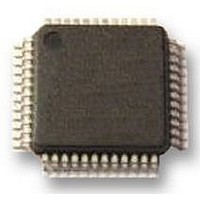
UPD78F0413GA-GAM-AX NEC, UPD78F0413GA-GAM-AX Datasheet - Page 12

UPD78F0413GA-GAM-AX
Manufacturer Part Number
UPD78F0413GA-GAM-AX
Description
8BIT UC, 32K FLASH, 1KB RAM, LCD
Manufacturer
NEC
Datasheet
1.UPD78F0413GA-GAM-AX.pdf
(562 pages)
Specifications of UPD78F0413GA-GAM-AX
Controller Family/series
UPD78F
No. Of I/o's
30
Ram Memory Size
1024Byte
Cpu Speed
10MHz
No. Of Timers
8
No. Of Pwm
RoHS Compliant
Core Size
8bit
Program Memory Size
32KB
Oscillator Type
External, Internal
Available stocks
Company
Part Number
Manufacturer
Quantity
Price
Company:
Part Number:
UPD78F0413GA-GAM-AX
Manufacturer:
ADI
Quantity:
882
Company:
Part Number:
UPD78F0413GA-GAM-AX
Manufacturer:
Renesas Electronics America
Quantity:
10 000
- Current page: 12 of 562
- Download datasheet (4Mb)
CHAPTER 18 KEY INTERRUPT FUNCTION ..................................................................................... 454
CHAPTER 19 STANDBY FUNCTION .................................................................................................. 456
CHAPTER 20 RESET FUNCTION........................................................................................................ 470
CHAPTER 21 POWER-ON-CLEAR CIRCUIT...................................................................................... 479
CHAPTER 22 LOW-VOLTAGE DETECTOR ....................................................................................... 485
CHAPTER 23 OPTION BYTE............................................................................................................... 503
CHAPTER 24 FLASH MEMORY .......................................................................................................... 508
12
18.1 Functions of Key Interrupt ...................................................................................................... 454
18.2 Configuration of Key Interrupt ................................................................................................ 454
18.3 Register Controlling Key Interrupt ......................................................................................... 455
19.1 Standby Function and Configuration ..................................................................................... 456
19.2 Standby Function Operation ................................................................................................... 459
20.1 Register for Confirming Reset Source ................................................................................... 478
21.1 Functions of Power-on-Clear Circuit...................................................................................... 479
21.2 Configuration of Power-on-Clear Circuit ............................................................................... 480
21.3 Operation of Power-on-Clear Circuit ...................................................................................... 480
21.4 Cautions for Power-on-Clear Circuit ...................................................................................... 483
22.1 Functions of Low-Voltage Detector........................................................................................ 485
22.2 Configuration of Low-Voltage Detector ................................................................................. 486
22.3 Registers Controlling Low-Voltage Detector......................................................................... 486
22.4 Operation of Low-Voltage Detector ........................................................................................ 489
22.5 Cautions for Low-Voltage Detector ........................................................................................ 500
23.1 Functions of Option Bytes ...................................................................................................... 503
23.2 Format of Option Byte ............................................................................................................. 505
24.1 Internal Memory Size Switching Register.............................................................................. 508
24.2 Writing with Flash memory programmer ............................................................................... 509
24.3 Programming Environment ..................................................................................................... 511
24.4 Communication Mode .............................................................................................................. 511
24.5 Connection of Pins on Board.................................................................................................. 513
19.1.1 Standby function ..........................................................................................................................456
19.1.2 Registers controlling standby function..........................................................................................457
19.2.1 HALT mode ..................................................................................................................................459
19.2.2 STOP mode .................................................................................................................................464
22.4.1 When used as reset .....................................................................................................................490
22.4.2 When used as interrupt ................................................................................................................495
24.5.1 FLMD0 pin ...................................................................................................................................513
24.5.2 Serial interface pins......................................................................................................................513
24.5.3 RESET pin ...................................................................................................................................515
24.5.4 Port pins.......................................................................................................................................515
User’s Manual U18698EJ1V0UD
Related parts for UPD78F0413GA-GAM-AX
Image
Part Number
Description
Manufacturer
Datasheet
Request
R

Part Number:
Description:
16/8 bit single-chip microcomputer
Manufacturer:
NEC
Datasheet:

Part Number:
Description:
Dual audio power amp circuit
Manufacturer:
NEC
Datasheet:

Part Number:
Description:
Dual comparator
Manufacturer:
NEC
Datasheet:

Part Number:
Description:
MOS type composite field effect transistor
Manufacturer:
NEC
Datasheet:

Part Number:
Description:
50 V/100 mA FET array incorporating 2 N-ch MOSFETs
Manufacturer:
NEC
Datasheet:

Part Number:
Description:
6-pin small MM high-frequency double transistor
Manufacturer:
NEC
Datasheet:

Part Number:
Description:
6-pin small MM high-frequency double transistor
Manufacturer:
NEC
Datasheet:

Part Number:
Description:
6-pin small MM high-frequency double transistor
Manufacturer:
NEC
Datasheet:

Part Number:
Description:
6-pin small MM high-frequency double transistor
Manufacturer:
NEC
Datasheet:

Part Number:
Description:
Twin transistors equipped with different model chips(6P small MM)
Manufacturer:
NEC
Datasheet:

Part Number:
Description:
Bipolar analog integrated circuit
Manufacturer:
NEC
Datasheet:


