EP3C10M164C8N Altera, EP3C10M164C8N Datasheet - Page 180
EP3C10M164C8N
Manufacturer Part Number
EP3C10M164C8N
Description
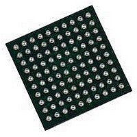
IC CYCLONE III FPGA 402MHZ BGA-164
Manufacturer
Altera
Series
Cyclone IIIr
Specifications of EP3C10M164C8N
No. Of Logic Blocks
645
Family Type
Cyclone III
No. Of I/o's
106
I/o Supply Voltage
3.3V
Operating Frequency Max
402MHz
Operating Temperature Range
0°C To +85°C
Family Name
Cyclone III
Number Of Logic Blocks/elements
10320
# I/os (max)
106
Frequency (max)
402MHz
Process Technology
65nm
Operating Supply Voltage (typ)
1.2V
Logic Cells
10320
Ram Bits
423936
Operating Supply Voltage (min)
1.15V
Operating Supply Voltage (max)
1.25V
Operating Temp Range
0C to 85C
Operating Temperature Classification
Commercial
Mounting
Surface Mount
Pin Count
164
Package Type
MBGA
Lead Free Status / RoHS Status
Lead free / RoHS Compliant
Lead Free Status / RoHS Status
Lead free / RoHS Compliant
Available stocks
Company
Part Number
Manufacturer
Quantity
Price


9–20
Cyclone III Device Handbook, Volume 1
Altera recommends putting a buffer before the DATA and DCLK output from the
master device to avoid signal strength and integrity issues. The buffer must not
significantly change the DATA-to-DCLK relationships or delay them with respect to
other AS signals (ASDI and nCS). Also, the buffer must only drive the slave devices to
ensure that the timing between the master device and the serial configuration device
is unaffected.
This configuration method supports both compressed and uncompressed .sofs.
Therefore, if the configuration bitstream size exceeds the capacity of a serial
configuration device, you can enable the compression feature in the .sof or you can
select a larger serial configuration device.
Guidelines for Connecting Serial Configuration Device to Cyclone III Device Family
on AS Interface
For single- and multi-device AS configurations, the board trace length and loading
between the supported serial configuration device and Cyclone III device family must
follow the recommendations listed in
Table 9–9. Maximum Trace Length and Loading for the AS Configuration
Estimating AS Configuration Time
AS configuration time is dominated by the time it takes to transfer data from the serial
configuration device to the Cyclone III device family. This serial interface is clocked
by the Cyclone III device family DCLK output (generated from an internal oscillator).
Equation 9–2
Cyclone III device family.
Equation 9–2.
Equation 9–3.
To estimate the typical configuration time, use the typical DCLK period shown in
Figure 9–7 on page
configuration time is 116.7 ms. Enabling compression reduces the amount of
configuration data that is sent to the Cyclone III device family, which also reduces
configuration time. On average, compression reduces configuration time by 50%.
RBF Size
3,500,000 bits
Device Family
Cyclone III
DATA[0]
AS Pins
DCLK
nCSO
ASDO
Chapter 9: Configuration, Design Security, and Remote System Upgrades in the Cyclone III Device Family
×
⎛
⎝
maximum DCLK period
- ----------------------------------------------------- -
×
and
⎛
⎝
50 ns
------------ -
1 bit
Equation 9–3
1 bit
9–22. With a typical DCLK period of 33.33 ns, the typical
Cyclone III Device Family to the Serial
⎞
⎠
Maximum Board Trace Length from the
=
Configuration Device (Inches)
175 ms
⎞
⎠
=
show the configuration time estimation for the
estimated maximum configuration time
10
10
10
10
Table
9–9.
© December 2009 Altera Corporation
Maximum Board Load (pF)
Configuration Features
15
30
30
30
Related parts for EP3C10M164C8N
Image
Part Number
Description
Manufacturer
Datasheet
Request
R

Part Number:
Description:
CYCLONE II STARTER KIT EP2C20N
Manufacturer:
Altera
Datasheet:


Part Number:
Description:
CPLD, EP610 Family, ECMOS Process, 300 Gates, 16 Macro Cells, 16 Reg., 16 User I/Os, 5V Supply, 35 Speed Grade, 24DIP
Manufacturer:
Altera Corporation
Datasheet:
Part Number:
Description:
CPLD, EP610 Family, ECMOS Process, 300 Gates, 16 Macro Cells, 16 Reg., 16 User I/Os, 5V Supply, 15 Speed Grade, 24DIP
Manufacturer:
Altera Corporation
Datasheet:
Part Number:
Description:
Manufacturer:
Altera Corporation
Datasheet:
Part Number:
Description:
CPLD, EP610 Family, ECMOS Process, 300 Gates, 16 Macro Cells, 16 Reg., 16 User I/Os, 5V Supply, 30 Speed Grade, 24DIP
Manufacturer:
Altera Corporation
Datasheet:
Part Number:
Description:
High-performance, low-power erasable programmable logic devices with 8 macrocells, 10ns
Manufacturer:
Altera Corporation
Datasheet:
Part Number:
Description:
High-performance, low-power erasable programmable logic devices with 8 macrocells, 7ns
Manufacturer:
Altera Corporation
Datasheet:
Part Number:
Description:
Classic EPLD
Manufacturer:
Altera Corporation
Datasheet:
Part Number:
Description:
High-performance, low-power erasable programmable logic devices with 8 macrocells, 10ns
Manufacturer:
Altera Corporation
Datasheet:
Part Number:
Description:
Manufacturer:
Altera Corporation
Datasheet:
Part Number:
Description:
Manufacturer:
Altera Corporation
Datasheet:
Part Number:
Description:
Manufacturer:
Altera Corporation
Datasheet:
Part Number:
Description:
CPLD, EP610 Family, ECMOS Process, 300 Gates, 16 Macro Cells, 16 Reg., 16 User I/Os, 5V Supply, 25 Speed Grade, 24DIP
Manufacturer:
Altera Corporation
Datasheet: