EP3C10M164C8N Altera, EP3C10M164C8N Datasheet - Page 300
EP3C10M164C8N
Manufacturer Part Number
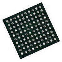
EP3C10M164C8N
Description
IC CYCLONE III FPGA 402MHZ BGA-164
Manufacturer
Altera
Series
Cyclone IIIr
Specifications of EP3C10M164C8N
No. Of Logic Blocks
645
Family Type
Cyclone III
No. Of I/o's
106
I/o Supply Voltage
3.3V
Operating Frequency Max
402MHz
Operating Temperature Range
0°C To +85°C
Family Name
Cyclone III
Number Of Logic Blocks/elements
10320
# I/os (max)
106
Frequency (max)
402MHz
Process Technology
65nm
Operating Supply Voltage (typ)
1.2V
Logic Cells
10320
Ram Bits
423936
Operating Supply Voltage (min)
1.15V
Operating Supply Voltage (max)
1.25V
Operating Temp Range
0C to 85C
Operating Temperature Classification
Commercial
Mounting
Surface Mount
Pin Count
164
Package Type
MBGA
Lead Free Status / RoHS Status
Lead free / RoHS Compliant
Lead Free Status / RoHS Status
Lead free / RoHS Compliant
Available stocks
Company
Part Number
Manufacturer
Quantity
Price


1–16
Table 1–20. Cyclone III Devices PLL Specifications
Cyclone III Device Handbook, Volume 2
f
t
t
t
t
t
t
t
t
t
t
f
Notes to
(1) V
(2) This parameter is limited in the Quartus II software by the I/O maximum frequency. The maximum I/O frequency is different for each I/O standard.
(3) The V
(4) A high input jitter directly affects the PLL output jitter. To have low PLL output clock jitter, you must provide a clean clock source, which is less than 200 ps.
(5) Peak-to-peak jitter with a probability level of 10
(6) With 100 MHz scanclk frequency.
OUT
OUTDUTY
LOCK
DLOCK
OUTJITTER_PERIOD_DEDC LK
OUTJITTER_CCJ _DEDCLK
OUTJITTER_PERIOD_IO
OUTJITTER_CCJ _IO
PLL_PSERR
ARESET
CONF IGPLL
SC ANC LK
(to global clock)
counter K value. Therefore, if the counter K has a value of 2, the frequency reported can be lower than the f
jitter of the PLL, when an input jitter of 30 ps is applied.
CC D_P LL
Table
CO
should always be connected to V
frequency reported by the Quartus II software in the PLL summary section of the compilation report takes into consideration the V
(5)
Symbol
(5)
1–20:
(5)
(5)
PLL output frequency (–6 speed grade)
PLL output frequency (–7 speed grade)
PLL output frequency (–8 speed grade)
Duty cycle for external clock output (when set to 50%)
Time required to lock from end of device configuration
Time required to lock dynamically (after switchover,
reconfiguring any non-post-scale counters/delays or
areset is deasserted)
Dedicated clock output period jitter
F
F
Dedicated clock output cycle-to-cycle jitter
F
F
Regular I/O period jitter
F
F
Regular I/O cycle-to-cycle jitter
F
F
Accuracy of PLL phase shift
Minimum pulse width on areset signal.
Time required to reconfigure scan chains for PLLs
scanclk frequency
OUT
OUT
OUT
OUT
OUT
OUT
OUT
OUT
≥ 100 MHz
< 100 MHz
≥ 100 MHz
< 100 MHz
≥ 100 MHz
< 100 MHz
≥ 100 MHz
< 100 MHz
C CINT
through decoupling capacitor and ferrite bead.
–12
(14 sigma, 99.99999999974404% confidence level). The output jitter specification applies to the intrinsic
(Note 1)
Parameter
(Part 2 of 2)
Chapter 1: Cyclone III Device Data Sheet
© January 2010 Altera Corporation
Min
—
—
—
45
—
—
—
—
—
—
—
—
—
—
—
10
—
—
V CO
specification.
3.5
Switching Characteristics
Typ
—
—
—
50
—
—
—
—
—
—
—
—
—
—
—
—
—
(6)
472.5
402.5
Max
450
300
300
650
650
±50
100
55
30
30
75
75
—
—
1
1
C O
SCANCLK
post-scale
cycles
Unit
MHz
MHz
MHz
MHz
mUI
mUI
mUI
mUI
ms
ms
ps
ps
ps
ps
ps
ns
%
Related parts for EP3C10M164C8N
Image
Part Number
Description
Manufacturer
Datasheet
Request
R

Part Number:
Description:
CYCLONE II STARTER KIT EP2C20N
Manufacturer:
Altera
Datasheet:


Part Number:
Description:
CPLD, EP610 Family, ECMOS Process, 300 Gates, 16 Macro Cells, 16 Reg., 16 User I/Os, 5V Supply, 35 Speed Grade, 24DIP
Manufacturer:
Altera Corporation
Datasheet:
Part Number:
Description:
CPLD, EP610 Family, ECMOS Process, 300 Gates, 16 Macro Cells, 16 Reg., 16 User I/Os, 5V Supply, 15 Speed Grade, 24DIP
Manufacturer:
Altera Corporation
Datasheet:
Part Number:
Description:
Manufacturer:
Altera Corporation
Datasheet:
Part Number:
Description:
CPLD, EP610 Family, ECMOS Process, 300 Gates, 16 Macro Cells, 16 Reg., 16 User I/Os, 5V Supply, 30 Speed Grade, 24DIP
Manufacturer:
Altera Corporation
Datasheet:
Part Number:
Description:
High-performance, low-power erasable programmable logic devices with 8 macrocells, 10ns
Manufacturer:
Altera Corporation
Datasheet:
Part Number:
Description:
High-performance, low-power erasable programmable logic devices with 8 macrocells, 7ns
Manufacturer:
Altera Corporation
Datasheet:
Part Number:
Description:
Classic EPLD
Manufacturer:
Altera Corporation
Datasheet:
Part Number:
Description:
High-performance, low-power erasable programmable logic devices with 8 macrocells, 10ns
Manufacturer:
Altera Corporation
Datasheet:
Part Number:
Description:
Manufacturer:
Altera Corporation
Datasheet:
Part Number:
Description:
Manufacturer:
Altera Corporation
Datasheet:
Part Number:
Description:
Manufacturer:
Altera Corporation
Datasheet:
Part Number:
Description:
CPLD, EP610 Family, ECMOS Process, 300 Gates, 16 Macro Cells, 16 Reg., 16 User I/Os, 5V Supply, 25 Speed Grade, 24DIP
Manufacturer:
Altera Corporation
Datasheet: