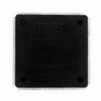
AT32AP7001-ALUT Atmel, AT32AP7001-ALUT Datasheet - Page 22

AT32AP7001-ALUT
Manufacturer Part Number
AT32AP7001-ALUT
Description
IC MCU 32BIT AVR32 208-LQFP
Manufacturer
Atmel
Series
AVR®32 AP7r
Specifications of AT32AP7001-ALUT
Core Processor
AVR
Core Size
32-Bit
Speed
150MHz
Connectivity
EBI/EMI, I²C, MMC, PS2, SPI, SSC, UART/USART, USB
Peripherals
AC'97, DMA, I²C, POR, PWM, WDT
Number Of I /o
90
Program Memory Type
ROMless
Ram Size
32K x 8
Voltage - Supply (vcc/vdd)
1.65 V ~ 1.95 V
Data Converters
D/A 2x16b
Oscillator Type
Internal
Operating Temperature
-40°C ~ 85°C
Package / Case
208-LQFP
Data Bus Width
32 bit
Data Ram Size
32 KB
Interface Type
EBI, ISI, MCI, PS2, SPI, TWI, USB
Maximum Clock Frequency
150 MHz
Number Of Programmable I/os
90
Number Of Timers
3
Maximum Operating Temperature
+ 85 C
Mounting Style
SMD/SMT
Minimum Operating Temperature
- 40 C
On-chip Dac
16 bit, 1 Channel
Package
208PQFP
Device Core
AVR32
Family Name
AT32
Maximum Speed
150 MHz
Operating Supply Voltage
1.8 V
For Use With
ATAVRONEKIT - KIT AVR/AVR32 DEBUGGER/PROGRMMRATNGW100 - KIT AVR32 NETWORK GATEWAYATSTK1000 - KIT STARTER FOR AVR32AP7000
Lead Free Status / RoHS Status
Lead free / RoHS Compliant
Eeprom Size
-
Program Memory Size
-
Lead Free Status / Rohs Status
Details
Available stocks
Company
Part Number
Manufacturer
Quantity
Price
Company:
Part Number:
AT32AP7001-ALUT
Manufacturer:
EVERLIGHT
Quantity:
12 000
- Current page: 22 of 829
- Download datasheet (12Mb)
7.3
7.3.1
7.3.2
32015G–AVR32–09/09
Programming Model
Register file configuration
Status register configuration
The AVR32B architecture specifies that the exception contexts may have a different number of
shadowed registers in different implementations.
in AVR32 AP.
Figure 7-3.
The Status Register (SR) is splitted into two halfwords, one upper and one lower, see
on page 22
code flags and the R, T and L bits, while the upper halfword contains information about the
mode and state the processor executes in. Refer to the AVR32 Architecture Manual for details.
Figure 7-4.
Bit 31
Application
Bit 31
0
-
SP_APP
FINTPC
INT0PC
INT1PC
SMPC
R12
R11
R10
PC
LR
R9
R8
R7
R6
R5
R4
R3
R2
R1
R0
SR
LC
1
0
-
Bit 0
H
0
and
Supervisor
Bit 31
RSR_SUP
RAR_SUP
The AVR32 AP Register File
The Status Register High Halfword
SP_SYS
FINTPC
INT0PC
INT1PC
0
J
SMPC
R12
R11
R10
Figure 7-5 on page
PC
LR
R9
R8
R7
R6
R5
R4
R3
R2
R1
R0
SR
DM
Bit 0
0
D
0
INT0
Bit 31
RSR_INT0
RAR_INT0
SP_SYS
FINTPC
INT0PC
INT1PC
SMPC
0
R12
R11
R10
-
PC
LR
R9
R8
R7
R6
R5
R4
R3
R2
R1
R0
SR
Bit 0
M2
0
23. The lower word contains the C, Z, N, V and Q condition
M1
0
INT1
Bit 31
RAR_INT1
RSR_INT1
SP_SYS
FINTPC
INT0PC
INT1PC
SMPC
R12
R11
R10
M0
PC
LR
R9
R8
R7
R6
R5
R4
R3
R2
R1
R0
SR
1
Bit 0
EM
1
I3M
Figure 7-3 on page 22
INT2
Bit 31
0
RAR_INT2
RSR_INT2
SP_SYS
FINTPC
SMPC
R12
R11
R10
SR
PC
LR
R9
R8
R7
R6
R5
R4
R3
R2
R1
R0
I2M
FE
0
Bit 0
I1M
0
INT3
Bit 31
I0M
RSR_INT3
RAR_INT3
0
R12_INT3
R11_INT3
R10_INT3
LR_INT3
SP_SYS
R9_INT3
R8_INT3
FINTPC
SMPC
PC
R7
R6
R5
R4
R3
R2
R1
R0
SR
Bit 16
GM
1
Bit 0
Bit name
Initial value
AT32AP7001
shows the model used
Global Interrupt Mask
Interrupt Level 0 Mask
Interrupt Level 1 Mask
Interrupt Level 2 Mask
Interrupt Level 3 Mask
Mode Bit 0
Mode Bit 1
Mode Bit 2
Reserved
Debug State
Debug State Mask
Java State
Java Handle
Reserved
Reserved
Exception Mask
Exception
Bit 31
RSR_EX
RAR_EX
SP_SYS
FINTPC
INT0PC
INT1PC
SMPC
R12
R11
R10
SR
PC
LR
R9
R8
R7
R6
R5
R4
R3
R2
R1
R0
Bit 0
Figure 7-4
NMI
Bit 31
RSR_NMI
RAR_NMI
SP_SYS
FINTPC
INT0PC
INT1PC
SMPC
R12
R11
R10
PC
LR
R9
R8
R7
R6
R5
R4
R3
R2
R1
R0
SR
Bit 0
22
Related parts for AT32AP7001-ALUT
Image
Part Number
Description
Manufacturer
Datasheet
Request
R

Part Number:
Description:
DEV KIT FOR AVR/AVR32
Manufacturer:
Atmel
Datasheet:

Part Number:
Description:
INTERVAL AND WIPE/WASH WIPER CONTROL IC WITH DELAY
Manufacturer:
ATMEL Corporation
Datasheet:

Part Number:
Description:
Low-Voltage Voice-Switched IC for Hands-Free Operation
Manufacturer:
ATMEL Corporation
Datasheet:

Part Number:
Description:
MONOLITHIC INTEGRATED FEATUREPHONE CIRCUIT
Manufacturer:
ATMEL Corporation
Datasheet:

Part Number:
Description:
AM-FM Receiver IC U4255BM-M
Manufacturer:
ATMEL Corporation
Datasheet:

Part Number:
Description:
Monolithic Integrated Feature Phone Circuit
Manufacturer:
ATMEL Corporation
Datasheet:

Part Number:
Description:
Multistandard Video-IF and Quasi Parallel Sound Processing
Manufacturer:
ATMEL Corporation
Datasheet:

Part Number:
Description:
High-performance EE PLD
Manufacturer:
ATMEL Corporation
Datasheet:

Part Number:
Description:
8-bit Flash Microcontroller
Manufacturer:
ATMEL Corporation
Datasheet:

Part Number:
Description:
2-Wire Serial EEPROM
Manufacturer:
ATMEL Corporation
Datasheet:


