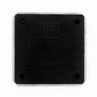
AT32AP7001-ALUT Atmel, AT32AP7001-ALUT Datasheet - Page 792

AT32AP7001-ALUT
Manufacturer Part Number
AT32AP7001-ALUT
Description
IC MCU 32BIT AVR32 208-LQFP
Manufacturer
Atmel
Series
AVR®32 AP7r
Specifications of AT32AP7001-ALUT
Core Processor
AVR
Core Size
32-Bit
Speed
150MHz
Connectivity
EBI/EMI, I²C, MMC, PS2, SPI, SSC, UART/USART, USB
Peripherals
AC'97, DMA, I²C, POR, PWM, WDT
Number Of I /o
90
Program Memory Type
ROMless
Ram Size
32K x 8
Voltage - Supply (vcc/vdd)
1.65 V ~ 1.95 V
Data Converters
D/A 2x16b
Oscillator Type
Internal
Operating Temperature
-40°C ~ 85°C
Package / Case
208-LQFP
Data Bus Width
32 bit
Data Ram Size
32 KB
Interface Type
EBI, ISI, MCI, PS2, SPI, TWI, USB
Maximum Clock Frequency
150 MHz
Number Of Programmable I/os
90
Number Of Timers
3
Maximum Operating Temperature
+ 85 C
Mounting Style
SMD/SMT
Minimum Operating Temperature
- 40 C
On-chip Dac
16 bit, 1 Channel
Package
208PQFP
Device Core
AVR32
Family Name
AT32
Maximum Speed
150 MHz
Operating Supply Voltage
1.8 V
For Use With
ATAVRONEKIT - KIT AVR/AVR32 DEBUGGER/PROGRMMRATNGW100 - KIT AVR32 NETWORK GATEWAYATSTK1000 - KIT STARTER FOR AVR32AP7000
Lead Free Status / RoHS Status
Lead free / RoHS Compliant
Eeprom Size
-
Program Memory Size
-
Lead Free Status / Rohs Status
Details
Available stocks
Company
Part Number
Manufacturer
Quantity
Price
Company:
Part Number:
AT32AP7001-ALUT
Manufacturer:
EVERLIGHT
Quantity:
12 000
- Current page: 792 of 829
- Download datasheet (12Mb)
38. Boot Sequence
38.1
38.2
32015G–AVR32–09/09
Starting of clocks
Fetching of initial instructions
This chapter summarizes the boot sequence of the AT32AP7001. The behaviour after power-up
is controlled by the Power Manager.
After power-up, the device will be held in a reset state by the Power-On Reset (POR) circuitry
until the voltage has reached the power-on reset rising threshold value (see Electrical Character-
istics for details). This ensures that all critical parts of the device are properly reset.
Once the power-on reset is complete, the device will use the XIN0 pin as clock source. XIN0 can
be connected either to an external clock, or a crystal. The OSCEN_N pin is connected either to
VDD or GND to inform the Power Manager on how the XIN0 pin is connected. If XIN0 receives a
signal from a crystal, dedicated circuitry in the Power Manager keeps the part in a reset state
until the oscillator connected to XIN0 has settled. If XIN0 receives an external clock, no such set-
tling delay is applied.
On system start-up, the PLLs are disabled. All clocks to all modules are running. No clocks have
a divided frequency, all parts of the system recieves a clock with the same frequency as the
XIN0 clock.
Note that the power-on reset will release reset at a lower voltage threshold than the minimum
specified operating voltage. If the voltage is not guaranteed to be stable by the time the device
starts executing, an external brown-out reset circuit should be used.
After reset has been released, the AVR32AP CPU starts fetching instructions from the reset
address, which is 0xA000_0000. This address lies in the P2 segment, which is non-translated,
non-cacheable, and permanently mapped to the physical address range 0x0000_0000 to
0x2000_0000. This means that the instruction being fetched from virtual address 0xA000_0000
is being fetched from physical address 0x0000_0000. Physical address 0x0000_0000 is
mapped to EBI SRAM CS0. This is the external memory the device boots from.
The code read from the SRAM CS0 memory is free to configure the system to use for example
the PLLs, to divide the frequency of the clock routed to some of the peripherals, and to gate the
clocks to unused peripherals.
AT32AP7001
792
Related parts for AT32AP7001-ALUT
Image
Part Number
Description
Manufacturer
Datasheet
Request
R

Part Number:
Description:
DEV KIT FOR AVR/AVR32
Manufacturer:
Atmel
Datasheet:

Part Number:
Description:
INTERVAL AND WIPE/WASH WIPER CONTROL IC WITH DELAY
Manufacturer:
ATMEL Corporation
Datasheet:

Part Number:
Description:
Low-Voltage Voice-Switched IC for Hands-Free Operation
Manufacturer:
ATMEL Corporation
Datasheet:

Part Number:
Description:
MONOLITHIC INTEGRATED FEATUREPHONE CIRCUIT
Manufacturer:
ATMEL Corporation
Datasheet:

Part Number:
Description:
AM-FM Receiver IC U4255BM-M
Manufacturer:
ATMEL Corporation
Datasheet:

Part Number:
Description:
Monolithic Integrated Feature Phone Circuit
Manufacturer:
ATMEL Corporation
Datasheet:

Part Number:
Description:
Multistandard Video-IF and Quasi Parallel Sound Processing
Manufacturer:
ATMEL Corporation
Datasheet:

Part Number:
Description:
High-performance EE PLD
Manufacturer:
ATMEL Corporation
Datasheet:

Part Number:
Description:
8-bit Flash Microcontroller
Manufacturer:
ATMEL Corporation
Datasheet:

Part Number:
Description:
2-Wire Serial EEPROM
Manufacturer:
ATMEL Corporation
Datasheet:


