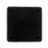
AT32AP7001-ALUT Atmel, AT32AP7001-ALUT Datasheet - Page 490

AT32AP7001-ALUT
Manufacturer Part Number
AT32AP7001-ALUT
Description
IC MCU 32BIT AVR32 208-LQFP
Manufacturer
Atmel
Series
AVR®32 AP7r
Specifications of AT32AP7001-ALUT
Core Processor
AVR
Core Size
32-Bit
Speed
150MHz
Connectivity
EBI/EMI, I²C, MMC, PS2, SPI, SSC, UART/USART, USB
Peripherals
AC'97, DMA, I²C, POR, PWM, WDT
Number Of I /o
90
Program Memory Type
ROMless
Ram Size
32K x 8
Voltage - Supply (vcc/vdd)
1.65 V ~ 1.95 V
Data Converters
D/A 2x16b
Oscillator Type
Internal
Operating Temperature
-40°C ~ 85°C
Package / Case
208-LQFP
Data Bus Width
32 bit
Data Ram Size
32 KB
Interface Type
EBI, ISI, MCI, PS2, SPI, TWI, USB
Maximum Clock Frequency
150 MHz
Number Of Programmable I/os
90
Number Of Timers
3
Maximum Operating Temperature
+ 85 C
Mounting Style
SMD/SMT
Minimum Operating Temperature
- 40 C
On-chip Dac
16 bit, 1 Channel
Package
208PQFP
Device Core
AVR32
Family Name
AT32
Maximum Speed
150 MHz
Operating Supply Voltage
1.8 V
For Use With
ATAVRONEKIT - KIT AVR/AVR32 DEBUGGER/PROGRMMRATNGW100 - KIT AVR32 NETWORK GATEWAYATSTK1000 - KIT STARTER FOR AVR32AP7000
Lead Free Status / RoHS Status
Lead free / RoHS Compliant
Eeprom Size
-
Program Memory Size
-
Lead Free Status / Rohs Status
Details
Available stocks
Company
Part Number
Manufacturer
Quantity
Price
Company:
Part Number:
AT32AP7001-ALUT
Manufacturer:
EVERLIGHT
Quantity:
12 000
- Current page: 490 of 829
- Download datasheet (12Mb)
28.5
28.5.1
28.5.2
28.6
28.6.1
Figure 28-2. SMC Connections to Static Memory Devices
28.6.2
32015G–AVR32–09/09
Product Dependencies
Functional Description
I/O Lines
Clocks
Application Example
External Memory Mapping
Static Memory
Controller
A1/NWR2/NBS2
NWR3/NBS3
NWR1/NBS1
NWR0/NWE
A0/NBS0
A2-A25
D0-D31
NCS1
NCS3
NCS4
NCS5
NCS0
NCS2
In order to use this module, other parts of the system must be configured correctly, as described
below.
The SMC signals pass through the External Bus Interface (EBI) module where they are multi-
plexed. The user must first configure the I/O Controller to assign the EBI pins corresponding to
SMC signals to their peripheral function. If the I/O lines of the EBI corresponding to SMC signals
are not used by the application, they can be used for other purposes by the I/O Controller.
The clock for the SMC bus interface (CLK_SMC) is generated by the Power Manager. This clock
is enabled at reset, and can be disabled in the Power Manager. It is recommended to disable the
SMC before disabling the clock, to avoid freezing the SMC in an undefined state.
The SMC provides up to 26 address lines, A[25:0]. This allows each chip select line to address
up to 64Mbytes of memory.
A1/NWR2/NBS2
NWR0/NWE
NRD
NRD
D16-D23
D0-D7
OE
OE
CS
WE
CS
WE
D0-D7
D0-D7
128K x 8
128K x 8
SRAM
SRAM
A0-A16
A0-A16
A2-A18
A2-A18
NWR1/NBS1
NWR3/NBS3
D24-D31
D8-D15
NRD
NRD
OE
OE
CS
WE
CS
WE
D0-D7
D0-D7
128K x 8
128K x 8
SRAM
SRAM
A0-A16
A0-A16
AT32AP7001
A2-A18
A2-A18
490
Related parts for AT32AP7001-ALUT
Image
Part Number
Description
Manufacturer
Datasheet
Request
R

Part Number:
Description:
DEV KIT FOR AVR/AVR32
Manufacturer:
Atmel
Datasheet:

Part Number:
Description:
INTERVAL AND WIPE/WASH WIPER CONTROL IC WITH DELAY
Manufacturer:
ATMEL Corporation
Datasheet:

Part Number:
Description:
Low-Voltage Voice-Switched IC for Hands-Free Operation
Manufacturer:
ATMEL Corporation
Datasheet:

Part Number:
Description:
MONOLITHIC INTEGRATED FEATUREPHONE CIRCUIT
Manufacturer:
ATMEL Corporation
Datasheet:

Part Number:
Description:
AM-FM Receiver IC U4255BM-M
Manufacturer:
ATMEL Corporation
Datasheet:

Part Number:
Description:
Monolithic Integrated Feature Phone Circuit
Manufacturer:
ATMEL Corporation
Datasheet:

Part Number:
Description:
Multistandard Video-IF and Quasi Parallel Sound Processing
Manufacturer:
ATMEL Corporation
Datasheet:

Part Number:
Description:
High-performance EE PLD
Manufacturer:
ATMEL Corporation
Datasheet:

Part Number:
Description:
8-bit Flash Microcontroller
Manufacturer:
ATMEL Corporation
Datasheet:

Part Number:
Description:
2-Wire Serial EEPROM
Manufacturer:
ATMEL Corporation
Datasheet:


