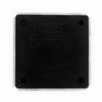
AT32AP7001-ALUT Atmel, AT32AP7001-ALUT Datasheet - Page 49

AT32AP7001-ALUT
Manufacturer Part Number
AT32AP7001-ALUT
Description
IC MCU 32BIT AVR32 208-LQFP
Manufacturer
Atmel
Series
AVR®32 AP7r
Specifications of AT32AP7001-ALUT
Core Processor
AVR
Core Size
32-Bit
Speed
150MHz
Connectivity
EBI/EMI, I²C, MMC, PS2, SPI, SSC, UART/USART, USB
Peripherals
AC'97, DMA, I²C, POR, PWM, WDT
Number Of I /o
90
Program Memory Type
ROMless
Ram Size
32K x 8
Voltage - Supply (vcc/vdd)
1.65 V ~ 1.95 V
Data Converters
D/A 2x16b
Oscillator Type
Internal
Operating Temperature
-40°C ~ 85°C
Package / Case
208-LQFP
Data Bus Width
32 bit
Data Ram Size
32 KB
Interface Type
EBI, ISI, MCI, PS2, SPI, TWI, USB
Maximum Clock Frequency
150 MHz
Number Of Programmable I/os
90
Number Of Timers
3
Maximum Operating Temperature
+ 85 C
Mounting Style
SMD/SMT
Minimum Operating Temperature
- 40 C
On-chip Dac
16 bit, 1 Channel
Package
208PQFP
Device Core
AVR32
Family Name
AT32
Maximum Speed
150 MHz
Operating Supply Voltage
1.8 V
For Use With
ATAVRONEKIT - KIT AVR/AVR32 DEBUGGER/PROGRMMRATNGW100 - KIT AVR32 NETWORK GATEWAYATSTK1000 - KIT STARTER FOR AVR32AP7000
Lead Free Status / RoHS Status
Lead free / RoHS Compliant
Eeprom Size
-
Program Memory Size
-
Lead Free Status / Rohs Status
Details
Available stocks
Company
Part Number
Manufacturer
Quantity
Price
Company:
Part Number:
AT32AP7001-ALUT
Manufacturer:
EVERLIGHT
Quantity:
12 000
- Current page: 49 of 829
- Download datasheet (12Mb)
8.8
8.8.1
8.8.1.1
32015G–AVR32–09/09
R{d, s, …}
Rd
Rs
Rb
Ri
Rp
IN{x, y, z}
INx
INy
INz
OUTd
OUTd
Pr
PrHi:PrLo
PC
LR
SP
PICORegList
disp
sa
[i]
[i:j]
Some instructions access or use doubleword operands. These operands must be placed in two consecutive register
addresses where the first register must be an even register. The even register contains the least significant part and
the odd register contains the most significant part. This ordering is reversed in comparison with how data is
organized in memory (where the most significant part would receive the lowest address) and is intentional.
PICO Instructions
PICO Instructions Nomenclature
Registers and Operands
The uppercase ‘R’ denotes a 32-bit (word) register.
The lowercase ‘d’ denotes the destination register number.
The lowercase ‘s’ denotes the source register number.
The lowercase ‘b’ denotes the base register number for indexed addressing modes.
The lowercase ‘i’ denotes the index register number for indexed addressing modes.
The lowercase ‘p’ denotes the pointer register number.
The uppercase ‘IN’ denotes a pixel in the INPIXn registers.
The lowercase ‘x’ denotes the first input pixel number for the PICO operation instructions.
The lowercase ‘y’ denotes the second input pixel number for the PICO operation instructions.
The lowercase ‘z’ denotes the third input pixel number for the PICO operation instructions.
The uppercase ‘OUT’ denotes a pixel in the OUTPIXn registers.
The lowercase ‘d’ denotes the destination pixel number for the PICO operation instructions.
PICO register. See
PICO register pair. Only register pairs corresponding to valid coprocessor double registers are valid.
E.g. INPIX1:INPIX2 (cr1:cr0). The low part must correspond to an even coprocessor register number
n and the high part must then correspond to coprocessor register n+1. See
for a mapping between PICO register names and coprocessor register numbers.
Program Counter, equal to R15
Link Register, equal to R14
Stack Pointer, equal to R13
Register List used in the picoldm and picostm instructions. See instruction description for which
register combinations are allowed in the register list.
Displacement
Shift amount
Denotes bit i in a immediate value. Example: imm6[4] denotes bit 4 in an 6-bit immediate value.
Denotes bit i to j in an immediate value.
Section 8.7.1 ”Register File” on page 31
for a complete list of registers.
AT32AP7001
Table 8-1 on page 31
49
Related parts for AT32AP7001-ALUT
Image
Part Number
Description
Manufacturer
Datasheet
Request
R

Part Number:
Description:
DEV KIT FOR AVR/AVR32
Manufacturer:
Atmel
Datasheet:

Part Number:
Description:
INTERVAL AND WIPE/WASH WIPER CONTROL IC WITH DELAY
Manufacturer:
ATMEL Corporation
Datasheet:

Part Number:
Description:
Low-Voltage Voice-Switched IC for Hands-Free Operation
Manufacturer:
ATMEL Corporation
Datasheet:

Part Number:
Description:
MONOLITHIC INTEGRATED FEATUREPHONE CIRCUIT
Manufacturer:
ATMEL Corporation
Datasheet:

Part Number:
Description:
AM-FM Receiver IC U4255BM-M
Manufacturer:
ATMEL Corporation
Datasheet:

Part Number:
Description:
Monolithic Integrated Feature Phone Circuit
Manufacturer:
ATMEL Corporation
Datasheet:

Part Number:
Description:
Multistandard Video-IF and Quasi Parallel Sound Processing
Manufacturer:
ATMEL Corporation
Datasheet:

Part Number:
Description:
High-performance EE PLD
Manufacturer:
ATMEL Corporation
Datasheet:

Part Number:
Description:
8-bit Flash Microcontroller
Manufacturer:
ATMEL Corporation
Datasheet:

Part Number:
Description:
2-Wire Serial EEPROM
Manufacturer:
ATMEL Corporation
Datasheet:


