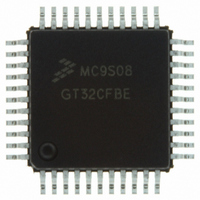
MC9S08GT32CFDE Freescale Semiconductor, MC9S08GT32CFDE Datasheet - Page 205

MC9S08GT32CFDE
Manufacturer Part Number
MC9S08GT32CFDE
Description
IC MCU 32K FLASH 20MHZ 48-QFN
Manufacturer
Freescale Semiconductor
Series
HCS08r
Specifications of MC9S08GT32CFDE
Core Processor
HCS08
Core Size
8-Bit
Speed
40MHz
Connectivity
I²C, SCI, SPI
Peripherals
LVD, POR, PWM, WDT
Number Of I /o
39
Program Memory Size
32KB (32K x 8)
Program Memory Type
FLASH
Ram Size
2K x 8
Voltage - Supply (vcc/vdd)
1.8 V ~ 3.6 V
Data Converters
A/D 8x10b
Oscillator Type
Internal
Operating Temperature
-40°C ~ 85°C
Package / Case
48-QFN
Controller Family/series
HCS08
No. Of I/o's
39
Ram Memory Size
2KB
Cpu Speed
40MHz
No. Of Timers
2
Rohs Compliant
Yes
For Use With
M68DEMO908GB60E - BOARD DEMO MC9S08GB60M68EVB908GB60E - BOARD EVAL FOR MC9S08GB60
Lead Free Status / RoHS Status
Lead free / RoHS Compliant
Eeprom Size
-
- Current page: 205 of 290
- Download datasheet (2Mb)
13.1
The inter-integrated circuit (IIC) provides a method of communication between a number of devices. The
interface is designed to operate up to 100 kbps with maximum bus loading and timing. The device is
capable of operating at higher baud rates, up to a maximum of clock/20, with reduced bus loading. The
maximum communication length and the number of devices that can be connected are limited by a
maximum bus capacitance of 400 pF.
For additional detail, please refer to volume 1 of the HCS08 Reference Manual, (Freescale Semiconductor
document order number HCS08RMv1/D).
13.1.1
The IIC includes these distinctive features:
13.1.2
The IIC functions the same in normal and monitor modes. A brief description of the IIC in the various
MCU modes is given here.
Freescale Semiconductor
•
•
•
•
•
•
•
•
•
•
•
•
•
•
Compatible with IIC bus standard
Multi-master operation
Software programmable for one of 64 different serial clock frequencies
Software selectable acknowledge bit
Interrupt driven byte-by-byte data transfer
Arbitration lost interrupt with automatic mode switching from master to slave
Calling address identification interrupt
START and STOP signal generation/detection
Repeated START signal generation
Acknowledge bit generation/detection
Bus busy detection
Run mode — This is the basic mode of operation. To conserve power in this mode, disable the
module.
Wait mode — The module will continue to operate while the MCU is in wait mode and can provide
a wake-up interrupt.
Stop mode — The IIC is inactive in stop3 mode for reduced power consumption. The STOP
instruction does not affect IIC register states. Stop1 and stop2 will reset the register contents.
Introduction
Features
Modes of Operation
MC9S08GB/GT Data Sheet, Rev. 2.3
Inter-Integrated Circuit (IIC) Module
205
Related parts for MC9S08GT32CFDE
Image
Part Number
Description
Manufacturer
Datasheet
Request
R
Part Number:
Description:
Manufacturer:
Freescale Semiconductor, Inc
Datasheet:
Part Number:
Description:
Manufacturer:
Freescale Semiconductor, Inc
Datasheet:
Part Number:
Description:
Manufacturer:
Freescale Semiconductor, Inc
Datasheet:
Part Number:
Description:
Manufacturer:
Freescale Semiconductor, Inc
Datasheet:
Part Number:
Description:
Manufacturer:
Freescale Semiconductor, Inc
Datasheet:
Part Number:
Description:
Manufacturer:
Freescale Semiconductor, Inc
Datasheet:
Part Number:
Description:
Manufacturer:
Freescale Semiconductor, Inc
Datasheet:
Part Number:
Description:
Manufacturer:
Freescale Semiconductor, Inc
Datasheet:
Part Number:
Description:
Manufacturer:
Freescale Semiconductor, Inc
Datasheet:
Part Number:
Description:
Manufacturer:
Freescale Semiconductor, Inc
Datasheet:
Part Number:
Description:
Manufacturer:
Freescale Semiconductor, Inc
Datasheet:
Part Number:
Description:
Manufacturer:
Freescale Semiconductor, Inc
Datasheet:
Part Number:
Description:
Manufacturer:
Freescale Semiconductor, Inc
Datasheet:
Part Number:
Description:
Manufacturer:
Freescale Semiconductor, Inc
Datasheet:
Part Number:
Description:
Manufacturer:
Freescale Semiconductor, Inc
Datasheet:


