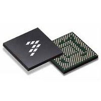
SC900841JVKR2 Freescale Semiconductor, SC900841JVKR2 Datasheet - Page 82

SC900841JVKR2
Manufacturer Part Number
SC900841JVKR2
Description
IC POWER MGT 338-MAPBGA
Manufacturer
Freescale Semiconductor
Specifications of SC900841JVKR2
Applications
PC's, PDA's
Operating Temperature
-40°C ~ 85°C
Mounting Type
Surface Mount
Package / Case
338-TBGA
Input Voltage
2.8 V to 4.4 V
Maximum Operating Temperature
+ 85 C
Minimum Operating Temperature
- 40 C
Lead Free Status / RoHS Status
Lead free / RoHS Compliant
Current - Supply
-
Voltage - Supply
-
Lead Free Status / Rohs Status
Lead free / RoHS Compliant
Available stocks
Company
Part Number
Manufacturer
Quantity
Price
Company:
Part Number:
SC900841JVKR2
Manufacturer:
Freescale Semiconductor
Quantity:
10 000
- Current page: 82 of 192
- Download datasheet (8Mb)
Table 38. FSLVYMXPACNTL Register Structure and Bits
VYMXPADISDSCH
VYMXPA Status/Control Registers and Bits Description
(Freescale Defined)
default state for each of these registers
VOTG
mode control DC/DC regulator with internal low side FET.
VOTG provides a fixed 5.0 V output voltage and capability to
supply up to 350 mA of drive current. It can be used
separately to support many applications that need a 5.0 V
supply voltage, as in motor drives. The following are the
typical loads for VOTG in SC900841 application
• Signaling/Status LED Drivers, See
• USB Bus (VBUS) while 900841 is operating in host mode
mode in USB-OTG systems. It offers the capability of up to
100 mA to supply to the USB Bus (VBUS). Due to the need
to isolate the USB Bus from the rest of the system when not
in use, an external PMOS switch (M
switch in a VOTG output to VBUS, as shown in
82
900841
FUNCTIONAL DEVICE OPERATION
POWER SUPPLIES
Reference the register map for read/write conditions and
This is a 2.0 MHz non-synchronous Boost PWM current-
as part of an UBS On-The-Go (OTG) System.
VOTG allows the 900841 the capability to support host
Optional Isolation Switch
If not used then
Connect OTGGTIN and OTGGT to GND
Then short V
Reserved
Name
FSLVYMXPACNTL (ADDR 0x1C7 - R/W - 0x01)
Description
OOTG
to FBOTG pin
Bits
7:1
0
C
Figure 38. VOTG Detailed Internal Block Diagram (Using OTG Host Mode)
VYMXPA Discharge FET Disable Signal
x0 = Discharged enabled
x1 = Discharged disabled
Reserved
OOTG
Load
V
OOTG
OTG
D
OTG
Description
Lighting
L
OTG
) will be used to
V
PWR
PGNDOTG
OTGGTIN
SWOTG
FBOTG
System.
OTGGT
Figure
C
INOTG
R
16.
SENSE
Discharge FET
Internal
Compensation
V
REF
Z1
Driver
V
V
V
REFUV
REFOV
REFSC
Driver
M
in the CHRGCNTL register. Reference
details into when the OTG host mode is enabled and M
enabled. OTG host mode is only possible when under battery
operation and no input power is connected. When OTG host
mode is enabled, the USBDET interrupt flag is ignored.
be populated, reducing the overall system cost, while the
OTGGTIN and OTGGT pins are grounded
drivers at 30 mA maximum each. These LED drivers may
turn on one at a time, at different drive values, or they may all
turn on together at the maximum driver value for each. Close
attention to VOTG transient response is in order here, to
account for these possible load changes.
an isolation switch. When M
either connect the feedback node after or before the switch.
Accuracy is maintained where the feedback node is
connected. The output capacitor C
either node, but is recommended to follow the feedback node
connection.
feedback node is taken after the switch. The discharge FET
is connected internally to the FBOTG pin. If M
then the discharge FET should be disabled by setting the
VOTGDISDSCH bit, since VOTG cannot be discharged due
to the lack of an isolation FET (the output is directly
connected to the input through the inductor and an external
diode).
and short-circuit protection.
EA
Z2
OTG
If OTG support is not needed, this switch does not need to
The rest of the VOTG load consists of a total of 6 LED
If OTG host mode is not used, M
VOTG can be discharged only if M
VOTG includes under-voltage, over-voltage, over-current,
SC
OC
UV
OV
enable is controlled through the CHRG and OTGB bits
Controller
Analog Integrated Circuit Device Data
OTG
AOACCTLVOTG
VOTGDISDSCH
VOTGFAULT
is used, then users can
CTLVOTG
OOTG
Freescale Semiconductor
OTG
OTG
Active State
can still be used as
can also connect to
Interface
is used and the
SPI
OTG
is not used,
for more
OTG
is
Related parts for SC900841JVKR2
Image
Part Number
Description
Manufacturer
Datasheet
Request
R
Part Number:
Description:
Ultra-mobile Platform Pmic
Manufacturer:
Freescale Semiconductor, Inc
Datasheet:

Part Number:
Description:
Sc900 Programmable Penta Uldo With Reset And I2c Interface
Manufacturer:
Semtech Corporation
Datasheet:
Part Number:
Description:
Manufacturer:
Freescale Semiconductor, Inc
Datasheet:
Part Number:
Description:
Manufacturer:
Freescale Semiconductor, Inc
Datasheet:
Part Number:
Description:
Manufacturer:
Freescale Semiconductor, Inc
Datasheet:
Part Number:
Description:
Manufacturer:
Freescale Semiconductor, Inc
Datasheet:
Part Number:
Description:
Manufacturer:
Freescale Semiconductor, Inc
Datasheet:
Part Number:
Description:
Manufacturer:
Freescale Semiconductor, Inc
Datasheet:
Part Number:
Description:
Manufacturer:
Freescale Semiconductor, Inc
Datasheet:
Part Number:
Description:
Manufacturer:
Freescale Semiconductor, Inc
Datasheet:
Part Number:
Description:
Manufacturer:
Freescale Semiconductor, Inc
Datasheet:
Part Number:
Description:
Manufacturer:
Freescale Semiconductor, Inc
Datasheet:
Part Number:
Description:
Manufacturer:
Freescale Semiconductor, Inc
Datasheet:
Part Number:
Description:
Manufacturer:
Freescale Semiconductor, Inc
Datasheet:
Part Number:
Description:
Manufacturer:
Freescale Semiconductor, Inc
Datasheet:


