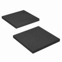
EP4SGX290KF40C3N Altera, EP4SGX290KF40C3N Datasheet - Page 771

EP4SGX290KF40C3N
Manufacturer Part Number
EP4SGX290KF40C3N
Description
IC STRATIX IV GX 290K 1517FBGA
Manufacturer
Altera
Series
Stratix® IV GXr
Datasheets
1.EP4SGX110DF29C3N.pdf
(80 pages)
2.EP4SGX110DF29C3N.pdf
(1154 pages)
3.EP4SGX110DF29C3N.pdf
(432 pages)
4.EP4SGX110DF29C3N.pdf
(22 pages)
5.EP4SGX110DF29C3N.pdf
(30 pages)
6.EP4SGX110DF29C3N.pdf
(72 pages)
Specifications of EP4SGX290KF40C3N
Number Of Logic Elements/cells
291200
Number Of Labs/clbs
11648
Total Ram Bits
17248
Number Of I /o
744
Voltage - Supply
0.87 V ~ 0.93 V
Mounting Type
Surface Mount
Operating Temperature
0°C ~ 85°C
Package / Case
1517-FBGA
Lead Free Status / RoHS Status
Lead free / RoHS Compliant
Number Of Gates
-
Other names
544-2624
Available stocks
Company
Part Number
Manufacturer
Quantity
Price
- EP4SGX110DF29C3N PDF datasheet
- EP4SGX110DF29C3N PDF datasheet #2
- EP4SGX110DF29C3N PDF datasheet #3
- EP4SGX110DF29C3N PDF datasheet #4
- EP4SGX110DF29C3N PDF datasheet #5
- EP4SGX110DF29C3N PDF datasheet #6
- Current page: 771 of 1154
- Download datasheet (32Mb)
Chapter 3: Configuring Multiple Protocols and Data Rates in Stratix IV Devices
Combining Channels Configured in Protocol Functional Modes
Combining Channels Configured in Protocol Functional Modes
February 2011 Altera Corporation
Combining Channels in Bonded Functional Modes
f
This section describes how to combine channels for various protocol functional
modes.
This section describes the combination requirements in the two variations of bonded
functional modes using transceiver PCS blocks. The two bonded functional modes
are:
■
■
Bonded ×4 Functional Mode
The combination requirements for Basic x4, Deterministic Latency ×4, and PCIe x4
functional modes (if you do not use the PCIe hard IP block) are similar.
In this mode, the transmitter channels are synchronized to reduce skew. The
Quartus II software shares the control from physical transmitter channel 0 with the
other transmitter channels in the transceiver block. Therefore, when you an create an
instance in this mode, the logical transmit channel 0 (tx_dataout[0] in the instance)
must be assigned by the physical channel location 0 in the transceiver block.
The central clock divider block in the CMU0 channel forwards the high-speed serial and
low-speed parallel clocks to the transmitter channels.
This clocking scheme is described in the “Bonded Channel Configurations” section of
the
Because you used the central clock divider, the are two restrictions on the channel
combinations:
1. If you configure channels in bonded ×4 functional mode, the remaining
“Bonded ×4 Functional
■
■
■
“Bonded x8 Functional Mode” on page
■
■
transmitter channels (regular or CMU channels) within the transceiver block can
be used only in Basic (PMA Direct) ×1 or ×N mode.
1
The receiver channels are clocked independently. Therefore, you can configure the
unused receiver channels within a transceiver block in any allowed configuration.
Transceiver Clocking in Stratix IV Devices
Basic mode with the sub protocol set to ×4
XAUI
PCIe mode with the sub protocol set to Gen1 ×4 or Gen2 ×4.
Basic mode with the sub protocol ×8
PCIe mode with the sub protocol ×8
If PCIe functional mode uses the PCIe hard IP block, the combination
requirements are different. For more information, refer to
Channels Using the PCIe hard IP Block with Other Channels” on page
Mode”—Examples of bonded ×4 mode:
3–20—Examples of bonded ×8 mode:
chapter.
Stratix IV Device Handbook Volume 2: Transceivers
“Combining
3–24.
3–17
Related parts for EP4SGX290KF40C3N
Image
Part Number
Description
Manufacturer
Datasheet
Request
R

Part Number:
Description:
CYCLONE II STARTER KIT EP2C20N
Manufacturer:
Altera
Datasheet:

Part Number:
Description:
CPLD, EP610 Family, ECMOS Process, 300 Gates, 16 Macro Cells, 16 Reg., 16 User I/Os, 5V Supply, 35 Speed Grade, 24DIP
Manufacturer:
Altera Corporation
Datasheet:

Part Number:
Description:
CPLD, EP610 Family, ECMOS Process, 300 Gates, 16 Macro Cells, 16 Reg., 16 User I/Os, 5V Supply, 15 Speed Grade, 24DIP
Manufacturer:
Altera Corporation
Datasheet:

Part Number:
Description:
Manufacturer:
Altera Corporation
Datasheet:

Part Number:
Description:
CPLD, EP610 Family, ECMOS Process, 300 Gates, 16 Macro Cells, 16 Reg., 16 User I/Os, 5V Supply, 30 Speed Grade, 24DIP
Manufacturer:
Altera Corporation
Datasheet:

Part Number:
Description:
High-performance, low-power erasable programmable logic devices with 8 macrocells, 10ns
Manufacturer:
Altera Corporation
Datasheet:

Part Number:
Description:
High-performance, low-power erasable programmable logic devices with 8 macrocells, 7ns
Manufacturer:
Altera Corporation
Datasheet:

Part Number:
Description:
Classic EPLD
Manufacturer:
Altera Corporation
Datasheet:

Part Number:
Description:
High-performance, low-power erasable programmable logic devices with 8 macrocells, 10ns
Manufacturer:
Altera Corporation
Datasheet:

Part Number:
Description:
Manufacturer:
Altera Corporation
Datasheet:

Part Number:
Description:
Manufacturer:
Altera Corporation
Datasheet:

Part Number:
Description:
Manufacturer:
Altera Corporation
Datasheet:

Part Number:
Description:
CPLD, EP610 Family, ECMOS Process, 300 Gates, 16 Macro Cells, 16 Reg., 16 User I/Os, 5V Supply, 25 Speed Grade, 24DIP
Manufacturer:
Altera Corporation
Datasheet:


