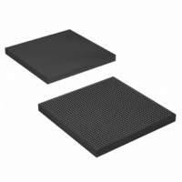
EP4SGX290KF40C3N Altera, EP4SGX290KF40C3N Datasheet - Page 947

EP4SGX290KF40C3N
Manufacturer Part Number
EP4SGX290KF40C3N
Description
IC STRATIX IV GX 290K 1517FBGA
Manufacturer
Altera
Series
Stratix® IV GXr
Datasheets
1.EP4SGX110DF29C3N.pdf
(80 pages)
2.EP4SGX110DF29C3N.pdf
(1154 pages)
3.EP4SGX110DF29C3N.pdf
(432 pages)
4.EP4SGX110DF29C3N.pdf
(22 pages)
5.EP4SGX110DF29C3N.pdf
(30 pages)
6.EP4SGX110DF29C3N.pdf
(72 pages)
Specifications of EP4SGX290KF40C3N
Number Of Logic Elements/cells
291200
Number Of Labs/clbs
11648
Total Ram Bits
17248
Number Of I /o
744
Voltage - Supply
0.87 V ~ 0.93 V
Mounting Type
Surface Mount
Operating Temperature
0°C ~ 85°C
Package / Case
1517-FBGA
Lead Free Status / RoHS Status
Lead free / RoHS Compliant
Number Of Gates
-
Other names
544-2624
Available stocks
Company
Part Number
Manufacturer
Quantity
Price
- EP4SGX110DF29C3N PDF datasheet
- EP4SGX110DF29C3N PDF datasheet #2
- EP4SGX110DF29C3N PDF datasheet #3
- EP4SGX110DF29C3N PDF datasheet #4
- EP4SGX110DF29C3N PDF datasheet #5
- EP4SGX110DF29C3N PDF datasheet #6
- Current page: 947 of 1154
- Download datasheet (32Mb)
Chapter 5: Dynamic Reconfiguration in Stratix IV Devices
Document Revision History
Document Revision History
Table 5–20. Document Revision History (Part 1 of 2)
February 2011 Altera Corporation
February 2011
March 2010
November 2009
June 2009
Date
Version
Table 5–20
3.0
3.2
3.1
2.1
■
■
■
■
■
■
■
■
■
■
■
■
■
■
■
■
■
■
■
Updated
Updated
Updated the
Reconfiguration Mode
Instances”,
and
Removed the “Continuous Mode for a Single Channel” and “Powerdown for a Single
Channel” sections.
Updated chapter title.
Applied new template.
Minor text edits.
Updated Table 5–5, Table 5–6, Table 5–15, Table 5–16, and Table 5–17.
Updated Figure 5–1, Figure 5–14, Figure 5–16, Figure 5–26, and Figure 5–37.
Updated the “Blocks Reconfigured in the Data Rate Division in Transmitter Mode”,
“Logical Channel Addressing of PMA-Only Channels”, “Central Control Unit
Reconfiguration Mode Details”, “EyeQ”, “Error Indication During Dynamic
Reconfiguration”, and “Functional Simulation of the Dynamic Reconfiguration Process”
sections.
Added a note to the “Central Control Unit Reconfiguration Mode Details” section.
Minor text edits.
Completely re-wrote and re-organized chapter.
Updated all graphics and tables.
Updated Figure 5–4, Figure 5–8, Figure 5–9, Figure 5–10, Figure 5–11, Figure 5–15,
Figure 5–22, Table 5–37, Table 5–38, Figure 5–44, Figure 5–47, Figure 5–48,
Figure 5–49, Figure 5–50, Figure 5–51, Figure 5–52, Figure 5–53, and Figure 5–54
Updated Table 5–2 and Table 5–31
Changed “logical_tx_pll_sel[1:0]” to “logical_tx_pll_sel” throughout
Updated “The reconfig_clk Clock Requirements for the ALTGX Instance and
ALTGX_RECONFIG Instance”, “The logical_tx_pll_sel and logical_tx_pll_sel_en Ports”,
“How to Use the logical_tx_pll_sel Port?”, and “When Can the logical_tx_pll_sel and
logical_tx_pll_sel_en Ports be Used?”
Minor text edits
lists the revision history for this chapter.
“Functional Simulation of the Dynamic Reconfiguration Process”
Table
Figure
“One Time Mode for a Single
“Transceiver Channel Reconfiguration Mode
5–5,
5–1.
Table
Details”,
5–6, and
“Connecting the ALTGX and ALTGX_RECONFIG
Table
Changes
5–16.
Channel”,
Stratix IV Device Handbook Volume 2: Transceivers
“Applying a .mif in the User
Details”.
“PMA Controls
sections.
Design”,
5–101
Related parts for EP4SGX290KF40C3N
Image
Part Number
Description
Manufacturer
Datasheet
Request
R

Part Number:
Description:
CYCLONE II STARTER KIT EP2C20N
Manufacturer:
Altera
Datasheet:

Part Number:
Description:
CPLD, EP610 Family, ECMOS Process, 300 Gates, 16 Macro Cells, 16 Reg., 16 User I/Os, 5V Supply, 35 Speed Grade, 24DIP
Manufacturer:
Altera Corporation
Datasheet:

Part Number:
Description:
CPLD, EP610 Family, ECMOS Process, 300 Gates, 16 Macro Cells, 16 Reg., 16 User I/Os, 5V Supply, 15 Speed Grade, 24DIP
Manufacturer:
Altera Corporation
Datasheet:

Part Number:
Description:
Manufacturer:
Altera Corporation
Datasheet:

Part Number:
Description:
CPLD, EP610 Family, ECMOS Process, 300 Gates, 16 Macro Cells, 16 Reg., 16 User I/Os, 5V Supply, 30 Speed Grade, 24DIP
Manufacturer:
Altera Corporation
Datasheet:

Part Number:
Description:
High-performance, low-power erasable programmable logic devices with 8 macrocells, 10ns
Manufacturer:
Altera Corporation
Datasheet:

Part Number:
Description:
High-performance, low-power erasable programmable logic devices with 8 macrocells, 7ns
Manufacturer:
Altera Corporation
Datasheet:

Part Number:
Description:
Classic EPLD
Manufacturer:
Altera Corporation
Datasheet:

Part Number:
Description:
High-performance, low-power erasable programmable logic devices with 8 macrocells, 10ns
Manufacturer:
Altera Corporation
Datasheet:

Part Number:
Description:
Manufacturer:
Altera Corporation
Datasheet:

Part Number:
Description:
Manufacturer:
Altera Corporation
Datasheet:

Part Number:
Description:
Manufacturer:
Altera Corporation
Datasheet:

Part Number:
Description:
CPLD, EP610 Family, ECMOS Process, 300 Gates, 16 Macro Cells, 16 Reg., 16 User I/Os, 5V Supply, 25 Speed Grade, 24DIP
Manufacturer:
Altera Corporation
Datasheet:


