M68EVB908GB60E Freescale Semiconductor, M68EVB908GB60E Datasheet - Page 176
M68EVB908GB60E
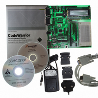
Manufacturer Part Number
M68EVB908GB60E
Description
BOARD EVAL FOR MC9S08GB60
Manufacturer
Freescale Semiconductor
Type
MCUr
Datasheet
1.M68EVB908GB60E.pdf
(290 pages)
Specifications of M68EVB908GB60E
Contents
Module and Misc Hardware
Processor To Be Evaluated
MC9S08GB
Data Bus Width
8 bit
Interface Type
RS-232
Silicon Manufacturer
Freescale
Core Architecture
HCS08
Core Sub-architecture
HCS08
Silicon Core Number
MC9S08
Silicon Family Name
S08GB
Kit Contents
GB60 Evaluation Kit
Rohs Compliant
Yes
For Use With/related Products
MC9S08GB60
Lead Free Status / RoHS Status
Lead free / RoHS Compliant


Serial Communications Interface (SCI) Module
When polling is used, this sequence is naturally satisfied in the normal course of the user program. If
hardware interrupts are used, SCIxS1 must be read in the interrupt service routine (ISR). Normally, this is
done in the ISR anyway to check for receive errors, so the sequence is automatically satisfied.
The IDLE status flag includes logic that prevents it from getting set repeatedly when the RxD1 line remains
idle for an extended period of time. IDLE is cleared by reading SCIxS1 while IDLE = 1 and then reading
SCIxD. After IDLE has been cleared, it cannot become set again until the receiver has received at least one
new character and has set RDRF.
If the associated error was detected in the received character that caused RDRF to be set, the error flags —
noise flag (NF), framing error (FE), and parity error flag (PF) — get set at the same time as RDRF. These
flags are not set in overrun cases.
If RDRF was already set when a new character is ready to be transferred from the receive shifter to the
receive data buffer, the overrun (OR) flag gets set instead and the data and any associated NF, FE, or PF
condition is lost.
11.8
The following sections describe additional SCI functions.
11.8.1
The SCI system (transmitter and receiver) can be configured to operate in 9-bit data mode by setting the
M control bit in SCIxC1. In 9-bit mode, there is a ninth data bit to the left of the MSB of the SCI data
register. For the transmit data buffer, this bit is stored in T8 in SCIxC3. For the receiver, the ninth bit is
held in R8 in SCIxC3.
When transmitting 9-bit data, write to the T8 bit before writing to SCIxD for coherent writes to the transmit
data buffer. If the bit value to be transmitted as the ninth bit of a new character is the same as for the
previous character, it is not necessary to write to T8 again. When data is transferred from the transmit data
buffer to the transmit shifter, the value in T8 is copied at the same time data is transferred from SCIxD to
the shifter.
When receiving 9-bit data, clear the RDRF bit by reading both R8 and SCIxD. R8 and SCIxD can be read
in either order.
9-bit data mode typically is used in conjunction with parity to allow eight bits of data plus the parity in the
ninth bit. Or it is used with address-mark wakeup so the ninth data bit can serve as the wakeup bit. In
custom protocols, the ninth bit can also serve as a software-controlled marker.
11.9
During all stop modes, clocks to the SCI module are halted.
In stop1 and stop2 modes, all SCI register data is lost and must be re-initialized upon recovery from these
two stop modes.
No SCI module registers are affected in stop3 mode.
176
Additional SCI Functions
Stop Mode Operation
8- and 9-Bit Data Modes
MC9S08GB/GT Data Sheet, Rev. 2.3
Freescale Semiconductor
Related parts for M68EVB908GB60E
Image
Part Number
Description
Manufacturer
Datasheet
Request
R

Part Number:
Description:
Manufacturer:
Freescale Semiconductor, Inc
Datasheet:
Part Number:
Description:
Manufacturer:
Freescale Semiconductor, Inc
Datasheet:
Part Number:
Description:
Manufacturer:
Freescale Semiconductor, Inc
Datasheet:
Part Number:
Description:
Manufacturer:
Freescale Semiconductor, Inc
Datasheet:
Part Number:
Description:
Manufacturer:
Freescale Semiconductor, Inc
Datasheet:
Part Number:
Description:
Manufacturer:
Freescale Semiconductor, Inc
Datasheet:
Part Number:
Description:
Manufacturer:
Freescale Semiconductor, Inc
Datasheet:
Part Number:
Description:
Manufacturer:
Freescale Semiconductor, Inc
Datasheet:
Part Number:
Description:
Manufacturer:
Freescale Semiconductor, Inc
Datasheet:
Part Number:
Description:
Manufacturer:
Freescale Semiconductor, Inc
Datasheet:
Part Number:
Description:
Manufacturer:
Freescale Semiconductor, Inc
Datasheet:
Part Number:
Description:
Manufacturer:
Freescale Semiconductor, Inc
Datasheet:
Part Number:
Description:
Manufacturer:
Freescale Semiconductor, Inc
Datasheet:
Part Number:
Description:
Manufacturer:
Freescale Semiconductor, Inc
Datasheet:
Part Number:
Description:
Manufacturer:
Freescale Semiconductor, Inc
Datasheet: