M68EVB908GB60E Freescale Semiconductor, M68EVB908GB60E Datasheet - Page 229
M68EVB908GB60E
Manufacturer Part Number
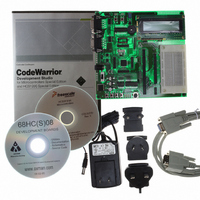
M68EVB908GB60E
Description
BOARD EVAL FOR MC9S08GB60
Manufacturer
Freescale Semiconductor
Type
MCUr
Datasheet
1.M68EVB908GB60E.pdf
(290 pages)
Specifications of M68EVB908GB60E
Contents
Module and Misc Hardware
Processor To Be Evaluated
MC9S08GB
Data Bus Width
8 bit
Interface Type
RS-232
Silicon Manufacturer
Freescale
Core Architecture
HCS08
Core Sub-architecture
HCS08
Silicon Core Number
MC9S08
Silicon Family Name
S08GB
Kit Contents
GB60 Evaluation Kit
Rohs Compliant
Yes
For Use With/related Products
MC9S08GB60
Lead Free Status / RoHS Status
Lead free / RoHS Compliant


14.4
The ATD module is reset on system reset. If the system reset signal is activated, the ATD registers are
initialized back to their reset state and the ATD module is powered down. This occurs as a function of the
register file initialization; the reset definition of the ATDPU bit (power down bit) is zero or disabled.
The MCU places the module back into an initialized state. If the module is performing a conversion, the
current conversion is terminated, the conversion complete flag is cleared, and the SAR register bits are
cleared. Any pending interrupts are also cancelled. Note that the control, test, and status registers are
initialized on reset; the initialized register state is defined in the register description section of this
specification.
Enabling the module (using the ATDPU bit) does not cause the module to reset since the register file is not
initialized. Finally, writing to control register ATD1C does not cause the module to reset; the current
conversion will be terminated.
14.5
The ATD module originates interrupt requests and the MCU handles or services these requests. Details on
how the ATD interrupt requests are handled can be found in
Configuration”.
The ATD interrupt function is enabled by setting the ATDIE bit in the ATD1SC register. When the ATDIE
bit is set, an interrupt is generated at the end of an ATD conversion and the ATD result registers (ATD1RH
and ATD1RL) contain the result data generated by the conversion. If the interrupt function is disabled
(ATDIE = 0), then the CCF flag must be polled to determine when a conversion is complete.
The interrupt will remain pending as long as the CCF flag is set. The CCF bit is cleared whenever the ATD
status and control (ATD1SC) register is written. The CCF bit is also cleared whenever the ATD result
registers (ATD1RH or ATD1RL) are read.
14.6
The ATD has seven registers which control ATD functions.
Refer to the direct-page register summary in
address assignments for all ATD registers. This section refers to registers and control bits only by their
names. A Freescale-provided equate or header file is used to translate these names into the appropriate
absolute addresses.
Freescale Semiconductor
Resets
Interrupts
ATD Registers and Control Bits
Interrupt
CCF
Enable
ATDIE
Local
MC9S08GB/GT Data Sheet, Rev. 2.3
Table 14-2. Interrupt Summary
Chapter 4,
Conversion complete
“Memory” of this data sheet for the absolute
Description
Chapter 5, “Resets, Interrupts, and System
Resets
229
Related parts for M68EVB908GB60E
Image
Part Number
Description
Manufacturer
Datasheet
Request
R

Part Number:
Description:
Manufacturer:
Freescale Semiconductor, Inc
Datasheet:
Part Number:
Description:
Manufacturer:
Freescale Semiconductor, Inc
Datasheet:
Part Number:
Description:
Manufacturer:
Freescale Semiconductor, Inc
Datasheet:
Part Number:
Description:
Manufacturer:
Freescale Semiconductor, Inc
Datasheet:
Part Number:
Description:
Manufacturer:
Freescale Semiconductor, Inc
Datasheet:
Part Number:
Description:
Manufacturer:
Freescale Semiconductor, Inc
Datasheet:
Part Number:
Description:
Manufacturer:
Freescale Semiconductor, Inc
Datasheet:
Part Number:
Description:
Manufacturer:
Freescale Semiconductor, Inc
Datasheet:
Part Number:
Description:
Manufacturer:
Freescale Semiconductor, Inc
Datasheet:
Part Number:
Description:
Manufacturer:
Freescale Semiconductor, Inc
Datasheet:
Part Number:
Description:
Manufacturer:
Freescale Semiconductor, Inc
Datasheet:
Part Number:
Description:
Manufacturer:
Freescale Semiconductor, Inc
Datasheet:
Part Number:
Description:
Manufacturer:
Freescale Semiconductor, Inc
Datasheet:
Part Number:
Description:
Manufacturer:
Freescale Semiconductor, Inc
Datasheet:
Part Number:
Description:
Manufacturer:
Freescale Semiconductor, Inc
Datasheet: