M68EVB908GB60E Freescale Semiconductor, M68EVB908GB60E Datasheet - Page 68
M68EVB908GB60E
Manufacturer Part Number
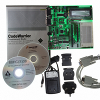
M68EVB908GB60E
Description
BOARD EVAL FOR MC9S08GB60
Manufacturer
Freescale Semiconductor
Type
MCUr
Datasheet
1.M68EVB908GB60E.pdf
(290 pages)
Specifications of M68EVB908GB60E
Contents
Module and Misc Hardware
Processor To Be Evaluated
MC9S08GB
Data Bus Width
8 bit
Interface Type
RS-232
Silicon Manufacturer
Freescale
Core Architecture
HCS08
Core Sub-architecture
HCS08
Silicon Core Number
MC9S08
Silicon Family Name
S08GB
Kit Contents
GB60 Evaluation Kit
Rohs Compliant
Yes
For Use With/related Products
MC9S08GB60
Lead Free Status / RoHS Status
Lead free / RoHS Compliant


Chapter 5 Resets, Interrupts, and System Configuration
When using the external oscillator in stop3 mode, it must be enabled in stop (OSCSTEN = 1) and
configured for low bandwidth operation (RANGE = 0).
The SRTISC register includes a read-only status flag, a write-only acknowledge bit, and a 3-bit control
value (RTIS2:RTIS1:RTIS0) used to select one of seven RTI periods. The RTI has a local interrupt enable,
RTIE, to allow masking of the real-time interrupt. The module can be disabled by writing 0:0:0 to
RTIS2:RTIS1:RTIS0 in which case the clock source input is disabled and no interrupts will be generated.
See
information about this register.
5.8
One 8-bit register in the direct page register space and eight 8-bit registers in the high-page register space
are related to reset and interrupt systems.
Refer to the direct-page register summary in
address assignments for all registers. This section refers to registers and control bits only by their names.
A Freescale-provided equate or header file is used to translate these names into the appropriate absolute
addresses.
Some control bits in the SOPT and SPMSC2 registers are related to modes of operation. Although brief
descriptions of these bits are provided here, the related functions are discussed in greater detail in
Chapter 3, “Modes of
5.8.1
This direct page register includes two unimplemented bits which always read 0, four read/write bits, one
read-only status bit, and one write-only bit. These bits are used to configure the IRQ function, report status,
and acknowledge IRQ events.
IRQEDG — Interrupt Request (IRQ) Edge Select
68
This read/write control bit is used to select the polarity of edges or levels on the IRQ pin that cause
IRQF to be set. The IRQMOD control bit determines whether the IRQ pin is sensitive to both edges
and levels or only edges. When the IRQ pin is enabled as the IRQ input and is configured to detect
rising edges, the optional pullup resistor is re-configured as an optional pulldown resistor.
Section 5.8.6, “System Real-Time Interrupt Status and Control Register
1 = IRQ is rising edge or rising edge/high-level sensitive.
0 = IRQ is falling edge or falling edge/low-level sensitive.
Reset, Interrupt, and System Control Registers and Control Bits
Interrupt Pin Request Status and Control Register (IRQSC)
Figure 5-2. Interrupt Request Status and Control Register (IRQSC)
Reset:
Read:
Write:
Operation.”
Bit 7
0
0
= Unimplemented or Reserved
MC9S08GB/GT Data Sheet, Rev. 2.3
6
0
0
Chapter 4,
IRQEDG
5
0
IRQPE
“Memory,” of this data sheet for the absolute
4
0
IRQF
3
0
IRQACK
2
0
0
(SRTISC),”
IRQIE
Freescale Semiconductor
1
0
for detailed
IRQMOD
Bit 0
0
Related parts for M68EVB908GB60E
Image
Part Number
Description
Manufacturer
Datasheet
Request
R

Part Number:
Description:
Manufacturer:
Freescale Semiconductor, Inc
Datasheet:
Part Number:
Description:
Manufacturer:
Freescale Semiconductor, Inc
Datasheet:
Part Number:
Description:
Manufacturer:
Freescale Semiconductor, Inc
Datasheet:
Part Number:
Description:
Manufacturer:
Freescale Semiconductor, Inc
Datasheet:
Part Number:
Description:
Manufacturer:
Freescale Semiconductor, Inc
Datasheet:
Part Number:
Description:
Manufacturer:
Freescale Semiconductor, Inc
Datasheet:
Part Number:
Description:
Manufacturer:
Freescale Semiconductor, Inc
Datasheet:
Part Number:
Description:
Manufacturer:
Freescale Semiconductor, Inc
Datasheet:
Part Number:
Description:
Manufacturer:
Freescale Semiconductor, Inc
Datasheet:
Part Number:
Description:
Manufacturer:
Freescale Semiconductor, Inc
Datasheet:
Part Number:
Description:
Manufacturer:
Freescale Semiconductor, Inc
Datasheet:
Part Number:
Description:
Manufacturer:
Freescale Semiconductor, Inc
Datasheet:
Part Number:
Description:
Manufacturer:
Freescale Semiconductor, Inc
Datasheet:
Part Number:
Description:
Manufacturer:
Freescale Semiconductor, Inc
Datasheet:
Part Number:
Description:
Manufacturer:
Freescale Semiconductor, Inc
Datasheet: