M68EVB908GB60E Freescale Semiconductor, M68EVB908GB60E Datasheet - Page 63
M68EVB908GB60E
Manufacturer Part Number
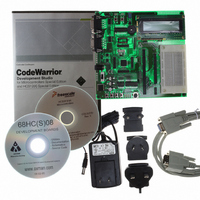
M68EVB908GB60E
Description
BOARD EVAL FOR MC9S08GB60
Manufacturer
Freescale Semiconductor
Type
MCUr
Datasheet
1.M68EVB908GB60E.pdf
(290 pages)
Specifications of M68EVB908GB60E
Contents
Module and Misc Hardware
Processor To Be Evaluated
MC9S08GB
Data Bus Width
8 bit
Interface Type
RS-232
Silicon Manufacturer
Freescale
Core Architecture
HCS08
Core Sub-architecture
HCS08
Silicon Core Number
MC9S08
Silicon Family Name
S08GB
Kit Contents
GB60 Evaluation Kit
Rohs Compliant
Yes
For Use With/related Products
MC9S08GB60
Lead Free Status / RoHS Status
Lead free / RoHS Compliant


When the CPU receives a qualified interrupt request, it completes the current instruction before responding
to the interrupt. The interrupt sequence follows the same cycle-by-cycle sequence as the SWI instruction
and consists of:
While the CPU is responding to the interrupt, the I bit is automatically set to avoid the possibility of another
interrupt interrupting the ISR itself (this is called nesting of interrupts). Normally, the I bit is restored to 0
when the CCR is restored from the value stacked on entry to the ISR. In rare cases, the I bit may be cleared
inside an ISR (after clearing the status flag that generated the interrupt) so that other interrupts can be
serviced without waiting for the first service routine to finish. This practice is not recommended for anyone
other than the most experienced programmers because it can lead to subtle program errors that are difficult
to debug.
The interrupt service routine ends with a return-from-interrupt (RTI) instruction which restores the CCR,
A, X, and PC registers to their pre-interrupt values by reading the previously saved information off the
stack.
When two or more interrupts are pending when the I bit is cleared, the highest priority source is serviced
first (see
5.5.1
Figure 5-1
(SP) points at the next available byte location on the stack. The current values of CPU registers are stored
on the stack starting with the low-order byte of the program counter (PCL) and ending with the CCR. After
stacking, the SP points at the next available location on the stack which is the address that is one less than
the address where the CCR was saved. The PC value that is stacked is the address of the instruction in the
main program that would have executed next if the interrupt had not occurred.
Freescale Semiconductor
•
•
•
•
Saving the CPU registers on the stack
Setting the I bit in the CCR to mask further interrupts
Fetching the interrupt vector for the highest-priority interrupt that is currently pending
Filling the instruction queue with the first three bytes of program information starting from the
address fetched from the interrupt vector locations
Table
shows the contents and organization of a stack frame. Before the interrupt, the stack pointer
Interrupt Stack Frame
For compatibility with the M68HC08, the H register is not automatically
saved and restored. It is good programming practice to push H onto the stack
at the start of the interrupt service routine (ISR) and restore it just before the
RTI that is used to return from the ISR.
5-1).
MC9S08GB/GT Data Sheet, Rev. 2.3
NOTE
Interrupts
63
Related parts for M68EVB908GB60E
Image
Part Number
Description
Manufacturer
Datasheet
Request
R

Part Number:
Description:
Manufacturer:
Freescale Semiconductor, Inc
Datasheet:
Part Number:
Description:
Manufacturer:
Freescale Semiconductor, Inc
Datasheet:
Part Number:
Description:
Manufacturer:
Freescale Semiconductor, Inc
Datasheet:
Part Number:
Description:
Manufacturer:
Freescale Semiconductor, Inc
Datasheet:
Part Number:
Description:
Manufacturer:
Freescale Semiconductor, Inc
Datasheet:
Part Number:
Description:
Manufacturer:
Freescale Semiconductor, Inc
Datasheet:
Part Number:
Description:
Manufacturer:
Freescale Semiconductor, Inc
Datasheet:
Part Number:
Description:
Manufacturer:
Freescale Semiconductor, Inc
Datasheet:
Part Number:
Description:
Manufacturer:
Freescale Semiconductor, Inc
Datasheet:
Part Number:
Description:
Manufacturer:
Freescale Semiconductor, Inc
Datasheet:
Part Number:
Description:
Manufacturer:
Freescale Semiconductor, Inc
Datasheet:
Part Number:
Description:
Manufacturer:
Freescale Semiconductor, Inc
Datasheet:
Part Number:
Description:
Manufacturer:
Freescale Semiconductor, Inc
Datasheet:
Part Number:
Description:
Manufacturer:
Freescale Semiconductor, Inc
Datasheet:
Part Number:
Description:
Manufacturer:
Freescale Semiconductor, Inc
Datasheet: