M68EVB908GB60E Freescale Semiconductor, M68EVB908GB60E Datasheet - Page 35
M68EVB908GB60E
Manufacturer Part Number
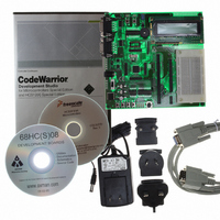
M68EVB908GB60E
Description
BOARD EVAL FOR MC9S08GB60
Manufacturer
Freescale Semiconductor
Type
MCUr
Datasheet
1.M68EVB908GB60E.pdf
(290 pages)
Specifications of M68EVB908GB60E
Contents
Module and Misc Hardware
Processor To Be Evaluated
MC9S08GB
Data Bus Width
8 bit
Interface Type
RS-232
Silicon Manufacturer
Freescale
Core Architecture
HCS08
Core Sub-architecture
HCS08
Silicon Core Number
MC9S08
Silicon Family Name
S08GB
Kit Contents
GB60 Evaluation Kit
Rohs Compliant
Yes
For Use With/related Products
MC9S08GB60
Lead Free Status / RoHS Status
Lead free / RoHS Compliant


Table 3-1
1
2
3.6.1
The stop1 mode provides the lowest possible standby power consumption by causing the internal circuitry
of the MCU to be powered down. Stop1 can be entered only if the LVD circuit is not enabled in stop modes
(either LVDE or LVDSE not set).
When the MCU is in stop1 mode, all internal circuits that are powered from the voltage regulator are turned
off. The voltage regulator is in a low-power standby state, as is the ATD.
Exit from stop1 is performed by asserting either of the wake-up pins on the MCU: RESET or IRQ. IRQ is
always an active low input when the MCU is in stop1, regardless of how it was configured before entering
stop1.
Entering stop1 mode automatically asserts LVD. Stop1 cannot be exited until V
must rise above the LVI rearm voltage).
Upon wake-up from stop1 mode, the MCU will start up as from a power-on reset (POR). The CPU will
take the reset vector.
3.6.2
The stop2 mode provides very low standby power consumption and maintains the contents of RAM and
the current state of all of the I/O pins. Stop2 can be entered only if the LVD circuit is not enabled in stop
modes (either LVDE or LVDSE not set).
Before entering stop2 mode, the user must save the contents of the I/O port registers, as well as any other
memory-mapped registers they want to restore after exit of stop2, to locations in RAM. Upon exit of stop2,
these values can be restored by user software before pin latches are opened.
When the MCU is in stop2 mode, all internal circuits that are powered from the voltage regulator are turned
off, except for the RAM. The voltage regulator is in a low-power standby state, as is the ATD. Upon entry
into stop2, the states of the I/O pins are latched. The states are held while in stop2 mode and after exiting
stop2 mode until a 1 is written to PPDACK in SPMSC2.
Freescale Semiconductor
Mode
Stop1
Stop2
Stop3
Either ATD stop mode or power-down mode depending on the state of ATDPU.
Crystal oscillator can be configured to run in stop3. Please see the ICG registers.
summarizes the behavior of the MCU in each of the stop modes.
PDC
Stop1 Mode
Stop2 Mode
1
1
0
PPDC
Don’t
care
0
1
CPU, Digital
Peripherals,
Standby
FLASH
Off
Off
MC9S08GB/GT Data Sheet, Rev. 2.3
Table 3-1. Stop Mode Behavior
Standby
Standby
RAM
Off
ICG
Off
Off
Off
2
Disabled
Disabled
Disabled
ATD
1
Regulator
Standby
Standby
Off
DD
> V
I/O Pins
States
States
Reset
held
held
LVDH/L
Optionally on
Optionally on
rising (V
Stop Modes
RTI
Off
DD
35
Related parts for M68EVB908GB60E
Image
Part Number
Description
Manufacturer
Datasheet
Request
R

Part Number:
Description:
Manufacturer:
Freescale Semiconductor, Inc
Datasheet:
Part Number:
Description:
Manufacturer:
Freescale Semiconductor, Inc
Datasheet:
Part Number:
Description:
Manufacturer:
Freescale Semiconductor, Inc
Datasheet:
Part Number:
Description:
Manufacturer:
Freescale Semiconductor, Inc
Datasheet:
Part Number:
Description:
Manufacturer:
Freescale Semiconductor, Inc
Datasheet:
Part Number:
Description:
Manufacturer:
Freescale Semiconductor, Inc
Datasheet:
Part Number:
Description:
Manufacturer:
Freescale Semiconductor, Inc
Datasheet:
Part Number:
Description:
Manufacturer:
Freescale Semiconductor, Inc
Datasheet:
Part Number:
Description:
Manufacturer:
Freescale Semiconductor, Inc
Datasheet:
Part Number:
Description:
Manufacturer:
Freescale Semiconductor, Inc
Datasheet:
Part Number:
Description:
Manufacturer:
Freescale Semiconductor, Inc
Datasheet:
Part Number:
Description:
Manufacturer:
Freescale Semiconductor, Inc
Datasheet:
Part Number:
Description:
Manufacturer:
Freescale Semiconductor, Inc
Datasheet:
Part Number:
Description:
Manufacturer:
Freescale Semiconductor, Inc
Datasheet:
Part Number:
Description:
Manufacturer:
Freescale Semiconductor, Inc
Datasheet: