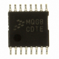
MC9S08QG8CDTE Freescale Semiconductor, MC9S08QG8CDTE Datasheet - Page 209

MC9S08QG8CDTE
Manufacturer Part Number
MC9S08QG8CDTE
Description
IC MCU 8K FLASH 10MHZ 16-TSSOP
Manufacturer
Freescale Semiconductor
Series
HCS08r
Datasheet
1.MC9S08QG8CDTER.pdf
(314 pages)
Specifications of MC9S08QG8CDTE
Core Processor
HCS08
Core Size
8-Bit
Speed
20MHz
Connectivity
I²C, SCI, SPI
Peripherals
LVD, POR, PWM, WDT
Number Of I /o
12
Program Memory Size
8KB (8K x 8)
Program Memory Type
FLASH
Ram Size
512 x 8
Voltage - Supply (vcc/vdd)
1.8 V ~ 3.6 V
Data Converters
A/D 8x10b
Oscillator Type
Internal
Operating Temperature
-40°C ~ 85°C
Package / Case
16-TSSOP
Cpu Family
HCS08
Device Core Size
8b
Frequency (max)
20MHz
Interface Type
I2C/SCI/SPI
Total Internal Ram Size
512Byte
# I/os (max)
12
Number Of Timers - General Purpose
1
Operating Supply Voltage (typ)
2.5/3.3V
Operating Supply Voltage (max)
3.6V
Operating Supply Voltage (min)
1.8V
On-chip Adc
8-chx10-bit
Instruction Set Architecture
CISC
Operating Temp Range
-40C to 85C
Operating Temperature Classification
Industrial
Mounting
Surface Mount
Pin Count
16
Package Type
TSSOP
Processor Series
S08QG
Core
HCS08
Data Bus Width
8 bit
Data Ram Size
512 B
Maximum Clock Frequency
20 MHz
Number Of Programmable I/os
12
Number Of Timers
1
Operating Supply Voltage
1.8 V to 3.6 V
Maximum Operating Temperature
+ 85 C
Mounting Style
SMD/SMT
3rd Party Development Tools
EWS08
Development Tools By Supplier
DEMO9S08QG8E
Minimum Operating Temperature
- 40 C
Package
16TSSOP
Family Name
HCS08
Maximum Speed
20 MHz
For Use With
DEMO9S08QG8E - BOARD DEMO FOR MC9S08QG8
Lead Free Status / RoHS Status
Lead free / RoHS Compliant
Eeprom Size
-
Lead Free Status / Rohs Status
Compliant
Available stocks
Company
Part Number
Manufacturer
Quantity
Price
Company:
Part Number:
MC9S08QG8CDTE
Manufacturer:
ABB
Quantity:
101
Company:
Part Number:
MC9S08QG8CDTE
Manufacturer:
Freescale Semiconductor
Quantity:
41 991
Part Number:
MC9S08QG8CDTE
Manufacturer:
FREESCALE
Quantity:
20 000
In the case of a framing error, the receiver is inhibited from receiving any new characters until the framing
error flag is cleared. The receive shift register continues to function, but a complete character cannot
transfer to the receive data buffer if FE is still set.
14.3.3.2
Receiver wakeup is a hardware mechanism that allows an SCI receiver to ignore the characters in a
message that is intended for a different SCI receiver. In such a system, all receivers evaluate the first
character(s) of each message, and as soon as they determine the message is intended for a different
receiver, they write logic 1 to the receiver wake up (RWU) control bit in SCIC2. When RWU = 1, it
inhibits setting of the status flags associated with the receiver, thus eliminating the software overhead for
handling the unimportant message characters. At the end of a message, or at the beginning of the next
message, all receivers automatically force RWU to 0 so all receivers wake up in time to look at the first
character(s) of the next message.
14.3.3.2.1
When WAKE = 0, the receiver is configured for idle-line wakeup. In this mode, RWU is cleared
automatically when the receiver detects a full character time of the idle-line level. The M control bit selects
8-bit or 9-bit data mode that determines how many bit times of idle are needed to constitute a full character
time (10 or 11 bit times because of the start and stop bits).
When the RWU bit is set, the idle character that wakes a receiver does not set the receiver idle bit, IDLE,
or the receive data register full flag, RDRF. It therefore will not generate an interrupt when this idle
character occurs. The receiver will wake up and wait for the next data transmission which will set RDRF
and generate an interrupt if enabled.
The idle-line type (ILT) control bit selects one of two ways to detect an idle line. When ILT = 0, the idle
bit counter starts after the start bit so the stop bit and any logic 1s at the end of a character count toward
the full character time of idle. When ILT = 1, the idle bit counter does not start until after a stop bit time,
so the idle detection is not affected by the data in the last character of the previous message.
14.3.3.2.2
When WAKE = 1, the receiver is configured for address-mark wakeup. In this mode, RWU is cleared
automatically when the receiver detects a logic 1 in the most significant bit of a received character (eighth
bit in M = 0 mode and ninth bit in M = 1 mode).
Address-mark wakeup allows messages to contain idle characters but requires that the MSB be reserved
for use in address frames. The logic 1 MSB of an address frame clears the receivers RWU bit before the
stop bit is received and sets the RDRF flag.
14.3.4
The SCI system has three separate interrupt vectors to reduce the amount of software needed to isolate the
cause of the interrupt. One interrupt vector is associated with the transmitter for TDRE and TC events.
Another interrupt vector is associated with the receiver for RDRF and IDLE events, and a third vector is
used for OR, NF, FE, and PF error conditions. Each of these eight interrupt sources can be separately
Freescale Semiconductor
Interrupts and Status Flags
Receiver Wakeup Operation
Idle-Line Wakeup
Address-Mark Wakeup
MC9S08QG8 and MC9S08QG4 Data Sheet, Rev. 5
Serial Communications Interface (S08SCIV3)
207


