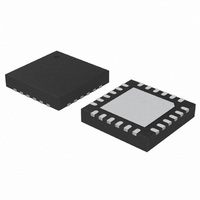
C8051F988-GM Silicon Laboratories Inc, C8051F988-GM Datasheet - Page 189

C8051F988-GM
Manufacturer Part Number
C8051F988-GM
Description
IC MCU 8BIT 4KB FLASH 24QFN
Manufacturer
Silicon Laboratories Inc
Series
C8051F9xxr
Specifications of C8051F988-GM
Program Memory Type
FLASH
Program Memory Size
4KB (4K x 8)
Package / Case
24-UQFN Exposed Pad, 24-HUQFN
Core Processor
8051
Core Size
8-Bit
Speed
25MHz
Connectivity
SMBus (2-Wire/I²C), SPI, UART/USART
Peripherals
Brown-out Detect/Reset, POR, PWM, Temp Sensor, WDT
Number Of I /o
17
Ram Size
512 x 8
Voltage - Supply (vcc/vdd)
1.8 V ~ 3.6 V
Data Converters
A/D 10x10b
Oscillator Type
Internal
Operating Temperature
-40°C ~ 85°C
Processor Series
C8051F9x
Core
8051
Data Ram Size
512 B
Interface Type
I2C, SMBus, Enhanced UART, Enhanced SPI
Maximum Clock Frequency
7 KHz
Number Of Programmable I/os
17
Number Of Timers
4
Operating Supply Voltage
2.4 V
Maximum Operating Temperature
+ 85 C
Mounting Style
SMD/SMT
3rd Party Development Tools
PK51, CA51, A51, ULINK2
Development Tools By Supplier
C8051F996DK
Minimum Operating Temperature
- 40 C
On-chip Adc
10 bit, 10 Channel
On-chip Dac
10 bit, 4 Channel
Lead Free Status / RoHS Status
Lead free / RoHS Compliant
Eeprom Size
-
Lead Free Status / Rohs Status
Lead free / RoHS Compliant
Other names
336-1959-5
- Current page: 189 of 322
- Download datasheet (3Mb)
19.3.2. External RC Mode
If an RC network is used as the external oscillator, the circuit should be configured as shown in
Figure 19.1, Option 2. The RC network should be added to XTAL2, and XTAL2 should be configured for
analog I/O with the digital output drivers disabled. XTAL1 is not affected in RC mode.
The capacitor should be no greater than 100 pF; however for very small capacitors, the total capacitance
may be dominated by parasitic capacitance in the PCB layout. The resistor should be no smaller than
10 k. The oscillation frequency can be determined by the following equation:
where
f = frequency of clock in MHzR = pull-up resistor value in k
V
To determine the required External Oscillator Frequency Control value (XFCN) in the OSCXCN Register,
first select the RC network value to produce the desired frequency of oscillation. For example, if the fre-
quency desired is 100 kHz, let R = 246 k and C = 50 pF:
where
f = frequency of clock in MHz
V
Referencing Table 19.2, the recommended XFCN setting is 010.
When the RC oscillator is first enabled, the external oscillator valid detector allows software to determine
when oscillation has stabilized. The recommended procedure for starting the RC oscillator is as follows:
1. Configure XTAL2 for analog I/O and disable the digital output drivers.
2. Configure and enable the external oscillator.
3. Poll for XTLVLD > 1.
4. Switch the system clock to the external oscillator.
DD
DD
f
= power supply voltage in VoltsC = capacitor value on the XTAL2 pin in pF
= power supply voltage in Volts
f
=
XFCN
=
000
001
010
100
101
011
110
111
1.23 10
------------------------ -
1.23 10
------------------------ -
R C
R
C
3
Table 19.2. Recommended XFCN Settings for RC and C modes
3
=
Frequency Range (RC
800 kHz f 1.6 MHz
1.6 MHz f 3.2 MHz
100 kHz f 200 kHz
200 kHz f 400 kHz
400 kHz f 800 kHz
50 kHz f 100 kHz
1.23 10
------------------------ -
25 kHz f 50 kHz
246 50
and C Mode)
Approximate
f 25 kHz
3
=
100 kHz
R = pull-up resistor value in k
C = capacitor value on the XTAL2 pin in pF
K Factor (C Mode)
Rev. 1.0
K Factor = 1590
K Factor = 0.87
K Factor = 180
K Factor = 664
K Factor = 2.6
K Factor = 7.7
K Factor = 22
K Factor = 65
C8051F99x-C8051F98x
Typical Supply Current/ Actual
242 µA, f = 890 kHz, C = 46 pF
1.0 mA, f = 2.0 MHz, C = 46 pF
4.6 mA, f = 6.8 MHz, C = 46 pF
32 µA, f = 270 kHz, C = 33 pF
82 µA, f = 310 kHz, C = 46 pF
5.5 µA, f = 33 kHz, C = 33 pF
3.0 µA, f = 11 kHz, C = 33 pF
13 µA, f = 98 kHz, C = 33 pF
(C Mode, VDD = 2.4 V)
Measured Frequency
189
Related parts for C8051F988-GM
Image
Part Number
Description
Manufacturer
Datasheet
Request
R
Part Number:
Description:
SMD/C°/SINGLE-ENDED OUTPUT SILICON OSCILLATOR
Manufacturer:
Silicon Laboratories Inc
Part Number:
Description:
Manufacturer:
Silicon Laboratories Inc
Datasheet:
Part Number:
Description:
N/A N/A/SI4010 AES KEYFOB DEMO WITH LCD RX
Manufacturer:
Silicon Laboratories Inc
Datasheet:
Part Number:
Description:
N/A N/A/SI4010 SIMPLIFIED KEY FOB DEMO WITH LED RX
Manufacturer:
Silicon Laboratories Inc
Datasheet:
Part Number:
Description:
N/A/-40 TO 85 OC/EZLINK MODULE; F930/4432 HIGH BAND (REV E/B1)
Manufacturer:
Silicon Laboratories Inc
Part Number:
Description:
EZLink Module; F930/4432 Low Band (rev e/B1)
Manufacturer:
Silicon Laboratories Inc
Part Number:
Description:
I°/4460 10 DBM RADIO TEST CARD 434 MHZ
Manufacturer:
Silicon Laboratories Inc
Part Number:
Description:
I°/4461 14 DBM RADIO TEST CARD 868 MHZ
Manufacturer:
Silicon Laboratories Inc
Part Number:
Description:
I°/4463 20 DBM RFSWITCH RADIO TEST CARD 460 MHZ
Manufacturer:
Silicon Laboratories Inc
Part Number:
Description:
I°/4463 20 DBM RADIO TEST CARD 868 MHZ
Manufacturer:
Silicon Laboratories Inc
Part Number:
Description:
I°/4463 27 DBM RADIO TEST CARD 868 MHZ
Manufacturer:
Silicon Laboratories Inc
Part Number:
Description:
I°/4463 SKYWORKS 30 DBM RADIO TEST CARD 915 MHZ
Manufacturer:
Silicon Laboratories Inc
Part Number:
Description:
N/A N/A/-40 TO 85 OC/4463 RFMD 30 DBM RADIO TEST CARD 915 MHZ
Manufacturer:
Silicon Laboratories Inc
Part Number:
Description:
I°/4463 20 DBM RADIO TEST CARD 169 MHZ
Manufacturer:
Silicon Laboratories Inc


