C8051F988-GM Silicon Laboratories Inc, C8051F988-GM Datasheet - Page 207
C8051F988-GM
Manufacturer Part Number
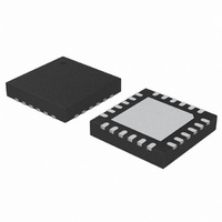
C8051F988-GM
Description
IC MCU 8BIT 4KB FLASH 24QFN
Manufacturer
Silicon Laboratories Inc
Series
C8051F9xxr
Specifications of C8051F988-GM
Program Memory Type
FLASH
Program Memory Size
4KB (4K x 8)
Package / Case
24-UQFN Exposed Pad, 24-HUQFN
Core Processor
8051
Core Size
8-Bit
Speed
25MHz
Connectivity
SMBus (2-Wire/I²C), SPI, UART/USART
Peripherals
Brown-out Detect/Reset, POR, PWM, Temp Sensor, WDT
Number Of I /o
17
Ram Size
512 x 8
Voltage - Supply (vcc/vdd)
1.8 V ~ 3.6 V
Data Converters
A/D 10x10b
Oscillator Type
Internal
Operating Temperature
-40°C ~ 85°C
Processor Series
C8051F9x
Core
8051
Data Ram Size
512 B
Interface Type
I2C, SMBus, Enhanced UART, Enhanced SPI
Maximum Clock Frequency
7 KHz
Number Of Programmable I/os
17
Number Of Timers
4
Operating Supply Voltage
2.4 V
Maximum Operating Temperature
+ 85 C
Mounting Style
SMD/SMT
3rd Party Development Tools
PK51, CA51, A51, ULINK2
Development Tools By Supplier
C8051F996DK
Minimum Operating Temperature
- 40 C
On-chip Adc
10 bit, 10 Channel
On-chip Dac
10 bit, 4 Channel
Lead Free Status / RoHS Status
Lead free / RoHS Compliant
Eeprom Size
-
Lead Free Status / Rohs Status
Lead free / RoHS Compliant
Other names
336-1959-5


20.3.2. Setting a SmaRTClock Alarm
The SmaRTClock alarm function compares the 32-bit value of SmaRTClock Timer to the value of the
ALARMn registers. An alarm event is triggered if the SmaRTClock timer is equal to the ALARMn registers.
If Auto Reset is enabled, the 32-bit timer will be cleared to zero one SmaRTClock cycle after the alarm
event.
The SmaRTClock alarm event can be configured to reset the MCU, wake it up from a low power mode, or
generate an interrupt. See Section “13. Interrupt Handler” on page 137, Section “15. Power Management”
on page 161, and Section “18. Reset Sources” on page 179 for more information.
The following steps can be used to set up a SmaRTClock Alarm:
1. Disable SmaRTClock Alarm Events (RTC0AEN = 0).
2. Set the ALARMn registers to the desired value.
3. Enable SmaRTClock Alarm Events (RTC0AEN = 1).
Notes:
1. The ALRM bit, which is used as the SmaRTClock Alarm Event flag, is cleared by disabling SmaRTClock Alarm
2. If AutoReset is disabled, disabling (RTC0AEN = 0) then Re-enabling Alarm Events (RTC0AEN = 1) after a
3. The SmaRTClock Alarm Event flag will remain asserted for a maximum of one SmaRTClock cycle. See Section
Events (RTC0AEN = 0).
SmaRTClock Alarm without modifying ALARMn registers will automatically schedule the next alarm after 2^32
SmaRTClock cycles (approximately 36 hours using a 32.768 kHz crystal).
“15. Power Management” on page 161 for information on how to capture a SmaRTClock Alarm event using a
flag which is not automatically cleared by hardware.
Rev. 1.0
C8051F99x-C8051F98x
207
Related parts for C8051F988-GM
Image
Part Number
Description
Manufacturer
Datasheet
Request
R

Part Number:
Description:
SMD/C°/SINGLE-ENDED OUTPUT SILICON OSCILLATOR
Manufacturer:
Silicon Laboratories Inc
Part Number:
Description:
Manufacturer:
Silicon Laboratories Inc
Datasheet:
Part Number:
Description:
N/A N/A/SI4010 AES KEYFOB DEMO WITH LCD RX
Manufacturer:
Silicon Laboratories Inc
Datasheet:
Part Number:
Description:
N/A N/A/SI4010 SIMPLIFIED KEY FOB DEMO WITH LED RX
Manufacturer:
Silicon Laboratories Inc
Datasheet:
Part Number:
Description:
N/A/-40 TO 85 OC/EZLINK MODULE; F930/4432 HIGH BAND (REV E/B1)
Manufacturer:
Silicon Laboratories Inc
Part Number:
Description:
EZLink Module; F930/4432 Low Band (rev e/B1)
Manufacturer:
Silicon Laboratories Inc
Part Number:
Description:
I°/4460 10 DBM RADIO TEST CARD 434 MHZ
Manufacturer:
Silicon Laboratories Inc
Part Number:
Description:
I°/4461 14 DBM RADIO TEST CARD 868 MHZ
Manufacturer:
Silicon Laboratories Inc
Part Number:
Description:
I°/4463 20 DBM RFSWITCH RADIO TEST CARD 460 MHZ
Manufacturer:
Silicon Laboratories Inc
Part Number:
Description:
I°/4463 20 DBM RADIO TEST CARD 868 MHZ
Manufacturer:
Silicon Laboratories Inc
Part Number:
Description:
I°/4463 27 DBM RADIO TEST CARD 868 MHZ
Manufacturer:
Silicon Laboratories Inc
Part Number:
Description:
I°/4463 SKYWORKS 30 DBM RADIO TEST CARD 915 MHZ
Manufacturer:
Silicon Laboratories Inc
Part Number:
Description:
N/A N/A/-40 TO 85 OC/4463 RFMD 30 DBM RADIO TEST CARD 915 MHZ
Manufacturer:
Silicon Laboratories Inc
Part Number:
Description:
I°/4463 20 DBM RADIO TEST CARD 169 MHZ
Manufacturer:
Silicon Laboratories Inc