HD64F36912GFH Renesas Electronics America, HD64F36912GFH Datasheet - Page 116
HD64F36912GFH
Manufacturer Part Number
HD64F36912GFH
Description
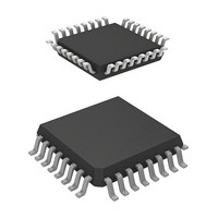
IC H8 MCU FLASH 8K 32-QFP
Manufacturer
Renesas Electronics America
Series
H8® H8/300H Tinyr
Datasheet
1.DF36912GFHV.pdf
(442 pages)
Specifications of HD64F36912GFH
Core Processor
H8/300H
Core Size
16-Bit
Speed
12MHz
Connectivity
I²C, SCI
Peripherals
LVD, POR, PWM, WDT
Number Of I /o
18
Program Memory Size
8KB (8K x 8)
Program Memory Type
FLASH
Ram Size
1.5K x 8
Voltage - Supply (vcc/vdd)
3 V ~ 5.5 V
Data Converters
A/D 4x10b
Oscillator Type
Internal
Operating Temperature
-20°C ~ 75°C
Package / Case
32-LQFP
Lead Free Status / RoHS Status
Contains lead / RoHS non-compliant
Eeprom Size
-
Available stocks
Company
Part Number
Manufacturer
Quantity
Price
Company:

Part Number:
HD64F36912GFH
Manufacturer:
Renesas Electronics America
Quantity:
10 000


Section 6 Power-Down Modes
6.1.1
SYSCR1 controls the power-down modes, as well as SYSCR2.
Rev. 3.00 Sep. 14, 2006 Page 86 of 408
REJ09B0105-0300
Bit
7
6
5
4
3 to 0
Bit Name
SSBY
STS2
STS1
STS0
System Control Register 1 (SYSCR1)
Initial
Value
0
0
0
0
All 0
R/W
R/W
R/W
R/W
R/W
Description
Software Standby
Specifies the operating mode to be entered after
executing the SLEEP instruction.
0: Shifts to sleep mode.
1: Shifts to standby mode.
For details, see table 6.2.
Standby Timer Select 2 to 0
These bits set the wait time from when the system clock
oscillator starts functioning until the clock is supplied, in
shifting from standby mode, to active mode or sleep
mode. During the wait time, this LSI automatically selects
the on-chip oscillator clock as its system clock and counts
the number of wait states. Select a wait time of 6.5 ms
(oscillation stabilization time) or longer, depending on the
operating frequency. Table 6.1 shows the relationship
between the STS2 to STS0 values and the wait time.
When using an external clock, set the wait time to be
100 s or longer in the F-ZTAT version. In the masked
ROM version, the minimum value (STS2 = STS1 = STS0
= 1) is recommended.
These bits also set the wait states for external oscillation
stabilization when system clock is switched from the on-
chip oscillator clock to the external clock by user
software.
The relationship between Nwait (number of wait states for
oscillation stabilization) and Nstby (number of wait states
for recovering to the standby mode) is as follows.
Nstby
Reserved
These bits are always read as 0.
Nwait
2
Nstby
Related parts for HD64F36912GFH
Image
Part Number
Description
Manufacturer
Datasheet
Request
R


Part Number:
Description:
KIT STARTER FOR M16C/29
Manufacturer:
Renesas Electronics America
Datasheet:

Part Number:
Description:
KIT STARTER FOR R8C/2D
Manufacturer:
Renesas Electronics America
Datasheet:

Part Number:
Description:
R0K33062P STARTER KIT
Manufacturer:
Renesas Electronics America
Datasheet:

Part Number:
Description:
KIT STARTER FOR R8C/23 E8A
Manufacturer:
Renesas Electronics America
Datasheet:

Part Number:
Description:
KIT STARTER FOR R8C/25
Manufacturer:
Renesas Electronics America
Datasheet:

Part Number:
Description:
KIT STARTER H8S2456 SHARPE DSPLY
Manufacturer:
Renesas Electronics America
Datasheet:

Part Number:
Description:
KIT STARTER FOR R8C38C
Manufacturer:
Renesas Electronics America
Datasheet:

Part Number:
Description:
KIT STARTER FOR R8C35C
Manufacturer:
Renesas Electronics America
Datasheet:

Part Number:
Description:
KIT STARTER FOR R8CL3AC+LCD APPS
Manufacturer:
Renesas Electronics America
Datasheet:
Part Number:
Description:
KIT STARTER FOR RX610
Manufacturer:
Renesas Electronics America
Datasheet:

Part Number:
Description:
KIT STARTER FOR R32C/118
Manufacturer:
Renesas Electronics America
Datasheet:

Part Number:
Description:
KIT DEV RSK-R8C/26-29
Manufacturer:
Renesas Electronics America
Datasheet:

Part Number:
Description:
KIT STARTER FOR SH7124
Manufacturer:
Renesas Electronics America
Datasheet:

Part Number:
Description:
KIT STARTER FOR H8SX/1622
Manufacturer:
Renesas Electronics America
Datasheet: