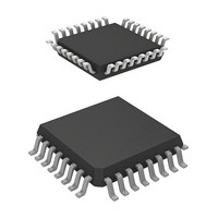
HD64F36912GFH Renesas Electronics America, HD64F36912GFH Datasheet - Page 91

HD64F36912GFH
Manufacturer Part Number
HD64F36912GFH
Description
IC H8 MCU FLASH 8K 32-QFP
Manufacturer
Renesas Electronics America
Series
H8® H8/300H Tinyr
Datasheet
1.DF36912GFHV.pdf
(442 pages)
Specifications of HD64F36912GFH
Core Processor
H8/300H
Core Size
16-Bit
Speed
12MHz
Connectivity
I²C, SCI
Peripherals
LVD, POR, PWM, WDT
Number Of I /o
18
Program Memory Size
8KB (8K x 8)
Program Memory Type
FLASH
Ram Size
1.5K x 8
Voltage - Supply (vcc/vdd)
3 V ~ 5.5 V
Data Converters
A/D 4x10b
Oscillator Type
Internal
Operating Temperature
-20°C ~ 75°C
Package / Case
32-LQFP
Lead Free Status / RoHS Status
Contains lead / RoHS non-compliant
Eeprom Size
-
Available stocks
Company
Part Number
Manufacturer
Quantity
Price
Company:
Part Number:
HD64F36912GFH
Manufacturer:
Renesas Electronics America
Quantity:
10 000
- Current page: 91 of 442
- Download datasheet (3Mb)
3.5
3.5.1
If an interrupt is accepted after a reset and before the stack pointer (SP) is initialized, the PC and
CCR will not be saved correctly, leading to a program crash. To prevent this, all interrupt requests,
including NMI, are disabled immediately after a reset. Since the first instruction of a program is
always executed immediately after the reset state ends, make sure that this instruction initializes
the stack pointer (example: MOV.W #xx: 16, SP).
3.5.2
When word data is accessed, the least significant bit of the address is regarded as 0. Access to the
stack always takes place in word size, so the stack pointer (SP: R7) should never indicate an odd
address. Use PUSH Rn (MOV.W Rn, @–SP) or POP Rn (MOV.W @SP+, Rn) to save or restore
register values.
3.5.3
When a port mode register is rewritten to switch the functions of external interrupt pins, IRQ3,
IRQ0, and WKP5, the interrupt request flag may be set to 1.
When switching a pin function, mask the interrupt before setting the bit in the port mode register.
After accessing the port mode register, execute at least one instruction (e.g., NOP), then clear the
interrupt request flag from 1 to 0.
Figure 3.4 shows a port mode register setting and interrupt request flag clearing procedure.
Figure 3.4 Port Mode Register Setting and Interrupt Request Flag Clearing Procedure
Usage Notes
Interrupts after Reset
Notes on Stack Area Use
Notes on Rewriting Port Mode Registers
Clear interrupt request flag to 0
Set port mode register bit
Execute NOP instruction
CCR I bit
CCR I bit
1
0
Interrupts masked. (Another possibility
is to disable the relevant interrupt in
interrupt enable register 1.)
After setting the port mode register bit,
first execute at least one instruction
(e.g., NOP), then clear the interrupt
request flag to 0
Interrupt mask cleared
Rev. 3.00 Sep. 14, 2006 Page 61 of 408
Section 3 Exception Handling
REJ09B0105-0300
Related parts for HD64F36912GFH
Image
Part Number
Description
Manufacturer
Datasheet
Request
R

Part Number:
Description:
KIT STARTER FOR M16C/29
Manufacturer:
Renesas Electronics America
Datasheet:

Part Number:
Description:
KIT STARTER FOR R8C/2D
Manufacturer:
Renesas Electronics America
Datasheet:

Part Number:
Description:
R0K33062P STARTER KIT
Manufacturer:
Renesas Electronics America
Datasheet:

Part Number:
Description:
KIT STARTER FOR R8C/23 E8A
Manufacturer:
Renesas Electronics America
Datasheet:

Part Number:
Description:
KIT STARTER FOR R8C/25
Manufacturer:
Renesas Electronics America
Datasheet:

Part Number:
Description:
KIT STARTER H8S2456 SHARPE DSPLY
Manufacturer:
Renesas Electronics America
Datasheet:

Part Number:
Description:
KIT STARTER FOR R8C38C
Manufacturer:
Renesas Electronics America
Datasheet:

Part Number:
Description:
KIT STARTER FOR R8C35C
Manufacturer:
Renesas Electronics America
Datasheet:

Part Number:
Description:
KIT STARTER FOR R8CL3AC+LCD APPS
Manufacturer:
Renesas Electronics America
Datasheet:

Part Number:
Description:
KIT STARTER FOR RX610
Manufacturer:
Renesas Electronics America
Datasheet:

Part Number:
Description:
KIT STARTER FOR R32C/118
Manufacturer:
Renesas Electronics America
Datasheet:

Part Number:
Description:
KIT DEV RSK-R8C/26-29
Manufacturer:
Renesas Electronics America
Datasheet:

Part Number:
Description:
KIT STARTER FOR SH7124
Manufacturer:
Renesas Electronics America
Datasheet:

Part Number:
Description:
KIT STARTER FOR H8SX/1622
Manufacturer:
Renesas Electronics America
Datasheet:


