HD64F36912GFH Renesas Electronics America, HD64F36912GFH Datasheet - Page 325
HD64F36912GFH
Manufacturer Part Number
HD64F36912GFH
Description
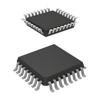
IC H8 MCU FLASH 8K 32-QFP
Manufacturer
Renesas Electronics America
Series
H8® H8/300H Tinyr
Datasheet
1.DF36912GFHV.pdf
(442 pages)
Specifications of HD64F36912GFH
Core Processor
H8/300H
Core Size
16-Bit
Speed
12MHz
Connectivity
I²C, SCI
Peripherals
LVD, POR, PWM, WDT
Number Of I /o
18
Program Memory Size
8KB (8K x 8)
Program Memory Type
FLASH
Ram Size
1.5K x 8
Voltage - Supply (vcc/vdd)
3 V ~ 5.5 V
Data Converters
A/D 4x10b
Oscillator Type
Internal
Operating Temperature
-20°C ~ 75°C
Package / Case
32-LQFP
Lead Free Status / RoHS Status
Contains lead / RoHS non-compliant
Eeprom Size
-
Available stocks
Company
Part Number
Manufacturer
Quantity
Price
Company:

Part Number:
HD64F36912GFH
Manufacturer:
Renesas Electronics America
Quantity:
10 000


(3)
Figure 17.6 shows the timing of the LVDI circuit. The LVDI circuit is enabled after a power-on
reset, however, the interrupt request is disabled. To enable the LVDI, the LVDDF and LVDUF
bits in LVDSR must be cleared to 0 and the LVDDE or LVDUE bit in LVDCR must be set to 1.
When using external compared voltage, write 0 to the VDDII bit in LVDCR, and wait for 50 s
(t
LVDUF bits to 0 and set the LVDDE or LVDUE bit to 1. After that, the output settings of ports
must be made. The initial value of the external compared voltages input on the ExtU and ExtD
pins must be higher than the Vexd voltage.
To cancel the LVDI, follow the procedures written in section 17.3.2 (4), Operating Procedures for
Enabling/Disabling LVDR and LVDI Circuits.
When the external comparison voltage of ExtD pin falls below the Vexd (D) (Typ. = 1.15 V)
voltage, the LVDI clears the LVDINT signal to 0 and sets the LVDDF bit in LVDSR to 1. If the
LVDDE bit is 1 at this time, an IRQ0 interrupt request is generated. In this case, the necessary
data must be saved in the external EEPROM, and a transition to standby mode or subsleep mode
must be made. Until this processing is completed, the power supply voltage must be higher than
the lower limit of the guaranteed operating voltage.
When the power-supply voltage does not fall below the Vreset1 (Typ. = 2.3 V) voltage and the
input voltage of the ExtU pin rises above Vexd (Typ. = 1.15 V) voltage, the LVDI circuit sets the
LVDINT signal to 1. If the LVDUE bit is 1 at this time, the LVDUF bit in LVDSR is set to 1 and
an IRQ0 interrupt request is generated.
If the power supply voltage falls below the Vreset1 (Typ. = 2.3 V) voltage, this LSI enters low-
voltage detection reset operation. When the voltages input on the ExtU and ExtD pins are used as
the compared voltage, ensure to use the LVDR (reset detection voltage: Typ. = 2.3 V) circuit.
LVDON
Low Voltage Detection Interrupt (LVDI) Circuit
(When Voltages Input via ExtU and ExtD Pins are used for Detection)
) given by a software timer until the detection circuit has settled. Then clear the LVDDF and
Section 17 Band-Gap Circuit, Power-On Reset, and Low-Voltage Detection Circuits
Rev. 3.00 Sep. 14, 2006 Page 295 of 408
REJ09B0105-0300
Related parts for HD64F36912GFH
Image
Part Number
Description
Manufacturer
Datasheet
Request
R


Part Number:
Description:
KIT STARTER FOR M16C/29
Manufacturer:
Renesas Electronics America
Datasheet:

Part Number:
Description:
KIT STARTER FOR R8C/2D
Manufacturer:
Renesas Electronics America
Datasheet:

Part Number:
Description:
R0K33062P STARTER KIT
Manufacturer:
Renesas Electronics America
Datasheet:

Part Number:
Description:
KIT STARTER FOR R8C/23 E8A
Manufacturer:
Renesas Electronics America
Datasheet:

Part Number:
Description:
KIT STARTER FOR R8C/25
Manufacturer:
Renesas Electronics America
Datasheet:

Part Number:
Description:
KIT STARTER H8S2456 SHARPE DSPLY
Manufacturer:
Renesas Electronics America
Datasheet:

Part Number:
Description:
KIT STARTER FOR R8C38C
Manufacturer:
Renesas Electronics America
Datasheet:

Part Number:
Description:
KIT STARTER FOR R8C35C
Manufacturer:
Renesas Electronics America
Datasheet:

Part Number:
Description:
KIT STARTER FOR R8CL3AC+LCD APPS
Manufacturer:
Renesas Electronics America
Datasheet:
Part Number:
Description:
KIT STARTER FOR RX610
Manufacturer:
Renesas Electronics America
Datasheet:

Part Number:
Description:
KIT STARTER FOR R32C/118
Manufacturer:
Renesas Electronics America
Datasheet:

Part Number:
Description:
KIT DEV RSK-R8C/26-29
Manufacturer:
Renesas Electronics America
Datasheet:

Part Number:
Description:
KIT STARTER FOR SH7124
Manufacturer:
Renesas Electronics America
Datasheet:

Part Number:
Description:
KIT STARTER FOR H8SX/1622
Manufacturer:
Renesas Electronics America
Datasheet: