HD64F36912GFH Renesas Electronics America, HD64F36912GFH Datasheet - Page 172
HD64F36912GFH
Manufacturer Part Number
HD64F36912GFH
Description
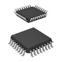
IC H8 MCU FLASH 8K 32-QFP
Manufacturer
Renesas Electronics America
Series
H8® H8/300H Tinyr
Datasheet
1.DF36912GFHV.pdf
(442 pages)
Specifications of HD64F36912GFH
Core Processor
H8/300H
Core Size
16-Bit
Speed
12MHz
Connectivity
I²C, SCI
Peripherals
LVD, POR, PWM, WDT
Number Of I /o
18
Program Memory Size
8KB (8K x 8)
Program Memory Type
FLASH
Ram Size
1.5K x 8
Voltage - Supply (vcc/vdd)
3 V ~ 5.5 V
Data Converters
A/D 4x10b
Oscillator Type
Internal
Operating Temperature
-20°C ~ 75°C
Package / Case
32-LQFP
Lead Free Status / RoHS Status
Contains lead / RoHS non-compliant
Eeprom Size
-
Available stocks
Company
Part Number
Manufacturer
Quantity
Price
Company:

Part Number:
HD64F36912GFH
Manufacturer:
Renesas Electronics America
Quantity:
10 000


Section 10 Timer B1
10.3
10.3.1
When bit TMB17 in TMB1 is cleared to 0, timer B1 functions as an 8-bit interval timer. Upon
reset, TCB1 is cleared to H'00 and bit TMB17 is cleared to 0, so up-counting and interval timing
resume immediately. The operating clock of timer B1 is selected from seven internal clock signals
output by prescaler S. The selection is made by the TMB12 to TMB10 bits in TMB1.
After the count value in TMB1 reaches H'FF, the next clock signal input causes timer B1 to
overflow, setting flag IRRTB1 in IRR2 to 1. If IENTB1 in IENR2 is 1, an interrupt is requested to
the CPU.
At overflow, TCB1 returns to H'00 and starts counting up again. During interval timer operation
(TMB17 = 0), when a value is set in TLB1, the same value is set in TCB1.
10.3.2
Setting bit TMB17 in TMB1 to 1 causes timer B1 to function as an 8-bit auto-reload timer. When
a reload value is set in TLB1, the same value is loaded into TCB1, becoming the value from which
TCB1 starts its count. After the count value in TCB1 reaches H'FF, the next clock signal input
causes timer B1 to overflow. The TLB1 value is then loaded into TCB1, and the count continues
from that value. The overflow period can be set within a range from 1 to 256 input clocks,
depending on the TLB1 value.
The clock sources and interrupts in auto-reload mode are the same as in interval mode. In auto-
reload mode (TMB17 = 1), when a new value is set in TLB1, the TLB1 value is also loaded into
TCB1.
Rev. 3.00 Sep. 14, 2006 Page 142 of 408
REJ09B0105-0300
Operation
Interval Timer Operation
Auto-Reload Timer Operation
Related parts for HD64F36912GFH
Image
Part Number
Description
Manufacturer
Datasheet
Request
R


Part Number:
Description:
KIT STARTER FOR M16C/29
Manufacturer:
Renesas Electronics America
Datasheet:

Part Number:
Description:
KIT STARTER FOR R8C/2D
Manufacturer:
Renesas Electronics America
Datasheet:

Part Number:
Description:
R0K33062P STARTER KIT
Manufacturer:
Renesas Electronics America
Datasheet:

Part Number:
Description:
KIT STARTER FOR R8C/23 E8A
Manufacturer:
Renesas Electronics America
Datasheet:

Part Number:
Description:
KIT STARTER FOR R8C/25
Manufacturer:
Renesas Electronics America
Datasheet:

Part Number:
Description:
KIT STARTER H8S2456 SHARPE DSPLY
Manufacturer:
Renesas Electronics America
Datasheet:

Part Number:
Description:
KIT STARTER FOR R8C38C
Manufacturer:
Renesas Electronics America
Datasheet:

Part Number:
Description:
KIT STARTER FOR R8C35C
Manufacturer:
Renesas Electronics America
Datasheet:

Part Number:
Description:
KIT STARTER FOR R8CL3AC+LCD APPS
Manufacturer:
Renesas Electronics America
Datasheet:
Part Number:
Description:
KIT STARTER FOR RX610
Manufacturer:
Renesas Electronics America
Datasheet:

Part Number:
Description:
KIT STARTER FOR R32C/118
Manufacturer:
Renesas Electronics America
Datasheet:

Part Number:
Description:
KIT DEV RSK-R8C/26-29
Manufacturer:
Renesas Electronics America
Datasheet:

Part Number:
Description:
KIT STARTER FOR SH7124
Manufacturer:
Renesas Electronics America
Datasheet:

Part Number:
Description:
KIT STARTER FOR H8SX/1622
Manufacturer:
Renesas Electronics America
Datasheet: