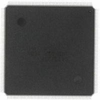
HD6417727F160CV Renesas Electronics America, HD6417727F160CV Datasheet - Page 42

HD6417727F160CV
Manufacturer Part Number
HD6417727F160CV
Description
IC SH MPU ROMLESS 240QFN
Manufacturer
Renesas Electronics America
Series
SuperH® SH7700r
Datasheet
1.HD6417727BP100CV.pdf
(1098 pages)
Specifications of HD6417727F160CV
Core Processor
SH-3 DSP
Core Size
32-Bit
Speed
160MHz
Connectivity
FIFO, SCI, SIO, SmartCard, USB
Peripherals
DMA, LCD, POR, WDT
Number Of I /o
104
Program Memory Type
ROMless
Ram Size
32K x 8
Voltage - Supply (vcc/vdd)
1.7 V ~ 2.05 V
Data Converters
A/D 6x10b; D/A 2x8b
Oscillator Type
Internal
Operating Temperature
-20°C ~ 75°C
Package / Case
240-QFP
Lead Free Status / RoHS Status
Lead free / RoHS Compliant
Eeprom Size
-
Program Memory Size
-
Available stocks
Company
Part Number
Manufacturer
Quantity
Price
Company:
Part Number:
HD6417727F160CV
Manufacturer:
RENESAS
Quantity:
37
Company:
Part Number:
HD6417727F160CV
Manufacturer:
RENESAS
Quantity:
753
- Current page: 42 of 1098
- Download datasheet (7Mb)
Figure 12.27 Basic Timing for PCMCIA Memory Card Interface Burst Access ........................ 355
Figure 12.28 Wait Timing for PCMCIA Memory Card Interface Burst Access ......................... 356
Figure 12.29 PCMCIA Space Assignment .................................................................................. 357
Figure 12.30 Basic Timing for PCMCIA I/O Card Interface ...................................................... 359
Figure 12.31 Wait Timing for PCMCIA I/O Card Interface ....................................................... 360
Figure 12.32 Dynamic Bus Sizing Timing for PCMCIA I/O Card Interface .............................. 361
Figure 12.33 Waits between Access Cycles ................................................................................ 363
Figure 12.34 Pins A25 to A0 Pull-Up Timing............................................................................. 364
Figure 12.35 Pins D31 to D0 Pull-Up Timing (Read Cycle)....................................................... 364
Figure 12.36 Pins D31 to D0 Pull-Up Timing (Write Cycle)...................................................... 365
Section 13 Li Bus State Controller (LBSC)
Figure 13.1 Block Diagram of Li Bus Architecture .................................................................. 377
Section 14 Direct Memory Access Controller (DMAC)
Figure 14.1 DMAC Block Diagram .......................................................................................... 381
Figure 14.2 DMAC Transfer Flowchart .................................................................................... 399
Figure 14.3 Operation in Round-Robin Mode........................................................................... 403
Figure 14.4 Channel Priority Order in Round-Robin Mode ...................................................... 404
Figure 14.5 Operation in Direct Address Mode......................................................................... 406
Figure 14.6 Example of DMA Transfer Timing in the Direct Address Mode
Figure 14.7 Example of DMA Transfer Timing in the Direct Address Mode
Figure 14.8 Example of DMA Transfer Timing in the Direct Address Mode
Figure 14.9 Operation in Indirect Address Mode (When the External Memory Space
Figure 14.10 Example of Transfer Timing in Indirect Address Mode
Figure 14.11 Data Flow in Single Address Mode........................................................................ 412
Figure 14.12 Example of DMA Transfer Timing in Single Address Mode ................................ 413
Figure 14.13 Example of DMA Transfer Timing in Single Address Mode (External Memory
Figure 14.14 Transfer Example in Cycle-Steal Mode ................................................................. 415
Figure 14.15 Example of Transfer in Burst Mode....................................................................... 415
Figure 14.16 Bus State in Multiple Channel Operation............................................................... 417
Figure 14.17 Cycle-Steal Mode, Level Input (CPU Access: 2 Cycles) ....................................... 420
Figure 14.18 Cycle-Steal Mode, Level Input (CPU Access: 3 Cycles) ....................................... 421
Rev.6.00 Mar. 27, 2009 Page xl of lvi
REJ09B0254-0600
(Transfer Source: Ordinary Memory, Transfer Destination: Ordinary Memory)... 407
(16-byte Transfer, Transfer Source: Ordinary Memory, Transfer Destination:
Ordinary Memory) ................................................................................................. 408
(16-byte Transfer, Transfer Source: Synchronous DRAM, Transfer Destination:
Ordinary Memory) ................................................................................................. 408
is Set to 16-bit Width) ............................................................................................ 410
(Transfer between External Memories, External Memory with 16-bit Width) ...... 411
Space (Ordinary Memory) → External Device with DACK) ................................ 414
Related parts for HD6417727F160CV
Image
Part Number
Description
Manufacturer
Datasheet
Request
R

Part Number:
Description:
KIT STARTER FOR M16C/29
Manufacturer:
Renesas Electronics America
Datasheet:

Part Number:
Description:
KIT STARTER FOR R8C/2D
Manufacturer:
Renesas Electronics America
Datasheet:

Part Number:
Description:
R0K33062P STARTER KIT
Manufacturer:
Renesas Electronics America
Datasheet:

Part Number:
Description:
KIT STARTER FOR R8C/23 E8A
Manufacturer:
Renesas Electronics America
Datasheet:

Part Number:
Description:
KIT STARTER FOR R8C/25
Manufacturer:
Renesas Electronics America
Datasheet:

Part Number:
Description:
KIT STARTER H8S2456 SHARPE DSPLY
Manufacturer:
Renesas Electronics America
Datasheet:

Part Number:
Description:
KIT STARTER FOR R8C38C
Manufacturer:
Renesas Electronics America
Datasheet:

Part Number:
Description:
KIT STARTER FOR R8C35C
Manufacturer:
Renesas Electronics America
Datasheet:

Part Number:
Description:
KIT STARTER FOR R8CL3AC+LCD APPS
Manufacturer:
Renesas Electronics America
Datasheet:

Part Number:
Description:
KIT STARTER FOR RX610
Manufacturer:
Renesas Electronics America
Datasheet:

Part Number:
Description:
KIT STARTER FOR R32C/118
Manufacturer:
Renesas Electronics America
Datasheet:

Part Number:
Description:
KIT DEV RSK-R8C/26-29
Manufacturer:
Renesas Electronics America
Datasheet:

Part Number:
Description:
KIT STARTER FOR SH7124
Manufacturer:
Renesas Electronics America
Datasheet:

Part Number:
Description:
KIT STARTER FOR H8SX/1622
Manufacturer:
Renesas Electronics America
Datasheet:

Part Number:
Description:
KIT DEV FOR SH7203
Manufacturer:
Renesas Electronics America
Datasheet:


