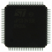
UPSD3433EB40U6 STMicroelectronics, UPSD3433EB40U6 Datasheet - Page 118

UPSD3433EB40U6
Manufacturer Part Number
UPSD3433EB40U6
Description
MCU 8BIT 8032 128KB FLASH 80TQFP
Manufacturer
STMicroelectronics
Series
µPSDr
Datasheet
1.UPSD3434EB40T6.pdf
(293 pages)
Specifications of UPSD3433EB40U6
Core Processor
8032
Core Size
8-Bit
Speed
40MHz
Connectivity
I²C, IrDA, SPI, UART/USART, USB
Peripherals
LVD, POR, PWM, WDT
Number Of I /o
46
Program Memory Size
160KB (160K x 8)
Program Memory Type
FLASH
Ram Size
8K x 8
Voltage - Supply (vcc/vdd)
3 V ~ 5.5 V
Data Converters
A/D 8x10b
Oscillator Type
Internal
Operating Temperature
-40°C ~ 85°C
Package / Case
80-TQFP, 80-VQFP
For Use With
497-5518 - EVAL BOARD RFID READER497-5046 - KIT TOOL FOR ST7/UPSD/STR7 MCU
Lead Free Status / RoHS Status
Lead free / RoHS Compliant
Eeprom Size
-
Other names
497-5660
Available stocks
Company
Part Number
Manufacturer
Quantity
Price
Company:
Part Number:
UPSD3433EB40U6
Manufacturer:
STMicroelectronics
Quantity:
10 000
- Current page: 118 of 293
- Download datasheet (5Mb)
I
23.4
23.5
23.5.1
23.5.2
118/293
2
C interface
The interface may operate as either a Master or a Slave within a given application,
controlled by firmware writing to SFRs.
By default after a reset, the I
SCL/P3.7 pins default to GPIO input mode, high impedance, so there is no I
interference. Before using the I
must be configured. This is discussed in
page
Bus arbitration
A Master device always samples the I
Master is asserting a logic 1. If the line is low at that time, the Master recognizes another
device is overriding its own transmission.
A Master may start a transfer only if the I
or more Masters may generate a START condition simultaneously. In this case, arbitration
takes place on the SDA line each time SCL is high. The Master that first senses that its bus
sample does not correspond to what it is driving (SDA line is low while it is asserting a high)
will immediately change from Master-Transmitter to Slave-Receiver mode. The arbitration
process can carry on for many bit times if both Masters are addressing the same Slave
device, and will continue into the data bits if both Masters are trying to be Master-
Transmitter. It is also possible for arbitration to carry on into the acknowledge bits if both
Masters are trying to be Master-Receiver. Because address and data information on the bus
is determined by the winning Master, no information is lost during the arbitration process.
Clock synchronization
Clock synchronization is used to synchronize arbitrating Masters, or used as a handshake
by a devices to slow down the data transfer.
Clock sync during arbitration
During bus arbitration between competing Masters, Master_X, with the longest low period
on SCL, will force Master_Y to wait until Master_X finishes its low period before Master_Y
proceeds to assert its high period on SCL. At this point, both Masters begin asserting their
high period on SCL simultaneously, and the Master with the shortest high period will be the
first to drive SCL for the next low period. In this scheme, the Master with the longest low
SCL period paces low times, and the Master with the shortest high SCL period paces the
high times, making synchronized arbitration possible.
Clock sync during handshaking
This allows receivers in different devices to handle various transfer rates, either at the byte-
level, or bit-level.
At the byte-level, a device may pause the transfer between bytes by holding SCL low to have
time to store the latest received byte or fetch the next byte to transmit.
At the bit-level, a Slave device may extend the low period of SCL by holding it low. Thus the
speed of any Master device will adapt to the internal operation of the Slave.
127.
2
C interface is in Master Receiver mode, and the SDA/P3.6 and
2
C interface, it must be initialized by firmware, and the pins
2
C bus to ensure a bus line is high whenever that
2
Section 23.13: I
C bus is not busy. However, it is possible that two
2
C operating sequences on
2
C bus
uPSD34xx
Related parts for UPSD3433EB40U6
Image
Part Number
Description
Manufacturer
Datasheet
Request
R

Part Number:
Description:
MCU 8BIT 8032 128KB FLASH 80TQFP
Manufacturer:
STMicroelectronics
Datasheet:

Part Number:
Description:
MCU 8BIT 8032 128KB FLASH 52TQFP
Manufacturer:
STMicroelectronics
Datasheet:

Part Number:
Description:
STMicroelectronics [RIPPLE-CARRY BINARY COUNTER/DIVIDERS]
Manufacturer:
STMicroelectronics
Datasheet:

Part Number:
Description:
STMicroelectronics [LIQUID-CRYSTAL DISPLAY DRIVERS]
Manufacturer:
STMicroelectronics
Datasheet:

Part Number:
Description:
BOARD EVAL FOR MEMS SENSORS
Manufacturer:
STMicroelectronics
Datasheet:

Part Number:
Description:
NPN TRANSISTOR POWER MODULE
Manufacturer:
STMicroelectronics
Datasheet:

Part Number:
Description:
TURBOSWITCH ULTRA-FAST HIGH VOLTAGE DIODE
Manufacturer:
STMicroelectronics
Datasheet:

Part Number:
Description:
Manufacturer:
STMicroelectronics
Datasheet:

Part Number:
Description:
DIODE / SCR MODULE
Manufacturer:
STMicroelectronics
Datasheet:

Part Number:
Description:
DIODE / SCR MODULE
Manufacturer:
STMicroelectronics
Datasheet:

Part Number:
Description:
Search -----> STE16N100
Manufacturer:
STMicroelectronics
Datasheet:

Part Number:
Description:
Search ---> STE53NA50
Manufacturer:
STMicroelectronics
Datasheet:


