MOD5234-100IR NetBurner Inc, MOD5234-100IR Datasheet - Page 571
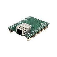
MOD5234-100IR
Manufacturer Part Number
MOD5234-100IR
Description
MOD5234 10/100 ETHERNET MODULE
Manufacturer
NetBurner Inc
Type
Controllers & Processorsr
Datasheets
1.MOD5272-100IR.pdf
(3 pages)
2.MOD5234-100IR.pdf
(4 pages)
3.MOD5234-100IR.pdf
(754 pages)
Specifications of MOD5234-100IR
Interface
I²C, SPI, UART
Voltage - Supply
2.5V
Mounting Type
Surface Mount
Package / Case
Module
Product
Modules
Lead Free Status / RoHS Status
Lead free / RoHS Compliant
Data Format
-
Baud Rates
-
Lead Free Status / Rohs Status
Lead free / RoHS Compliant
Other names
Q4483564


Figure 27-1
Section 27.5, “Memory Map/Register
27.4
The I
transfer. For I
open collector outputs. The logic AND function is exercised on both lines with external pull-up
resistors.
Out of reset, the I
or responding to a slave transmit address, the I
state. See
Normally, a standard communication is composed of four parts: START signal, slave address
transmission, data transfer, and STOP signal. These are discussed in the following sections.
27.4.1 START Signal
When no other device is bus master (both I2C_SCL and I2C_SDA lines are at logic high), a device
can initiate communication by sending a START signal (see A in
is defined as a high-to-low transition of I2C_SDA while I2C_SCL is high. This signal denotes the
beginning of a data transfer (each data transfer can be several bytes long) and awakens all slaves.
Freescale Semiconductor
• I
• I
• I
• I
• I
I2C_SDA
I2C_SCL
2
C module uses a serial data line (I2C_SDA) and a serial clock line (I2C_SCL) for data
2
2
2
2
2
A
C address register (I2ADR)
C frequency divider register (I2FDR)
C control register (I2CR)
C status register (I2SR)
C data I/O register (I2DR)
Section 27.6.1, “Initialization
I
2
START
Signal
C System Configuration
shows the relationships of the below I
2
C compliance, all devices connected to these two signals must have open drain or
AD7 AD6 AD5 AD4 AD3 AD2 AD1 R/W
msb
1
2
C default state is as a slave receiver. Thus, when not programmed to be a master
2
Figure 27-2. I
Calling Address
3
B
4
5
MCF5235 Reference Manual, Rev. 2
6
2
C Standard Communication Protocol
(Byte complete)
7
Definition":
Interrupt bit set
Sequence,” for exceptions.
R/W ACK
lsb
8
C
Bit
9
2
C module should return to the default slave receiver
D
XXX
I2C_SCL held low while
Interrupt is serviced
msb
D7 D6 D5
1
2
E
C registers, which are described in
2
3
Data Byte
Figure
D4 D3
4
5
27-2). A START signal
D2 D1
6
7
I
2
C System Configuration
lsb
D0
8
ACK
No
Bit
9
STOP
Signal
F
27-3
Related parts for MOD5234-100IR
Image
Part Number
Description
Manufacturer
Datasheet
Request
R

Part Number:
Description:
MCU, MPU & DSP Development Tools MOD5234 MODULE
Manufacturer:
NetBurner Inc
Datasheet:

Part Number:
Description:
MCU, MPU & DSP Development Tools MOD5234 Core Module Development Kit
Manufacturer:
NetBurner Inc
Datasheet:

Part Number:
Description:
BOARD SERIAL-ETHERNET 512K FLASH
Manufacturer:
NetBurner Inc
Datasheet:

Part Number:
Description:
PROCESSOR MODULE FLASH MOD5272
Manufacturer:
NetBurner Inc
Datasheet:

Part Number:
Description:
PROCESSOR MODULE 512KB FLASH
Manufacturer:
NetBurner Inc
Datasheet:

Part Number:
Description:
DUAL PORT SERIAL-ETHERNET
Manufacturer:
NetBurner Inc
Datasheet:

Part Number:
Description:
PROCESSOR MODULE FLASH
Manufacturer:
NetBurner Inc
Datasheet:

Part Number:
Description:
PROCESSOR MODULE 512KB FLASH
Manufacturer:
NetBurner Inc
Datasheet:

Part Number:
Description:
KIT DEVELOP NETWORK FOR MOD5282
Manufacturer:
NetBurner Inc
Datasheet:

Part Number:
Description:
KIT DEVELOP NETWORK FOR MOD5272
Manufacturer:
NetBurner Inc
Datasheet:

Part Number:
Description:
DUAL PORT SERIAL-ETHERNET
Manufacturer:
NetBurner Inc
Datasheet:

Part Number:
Description:
Ethernet Modules & Development Tools 32 Bit 66MHz 40 Pin DIP Industrial Temp
Manufacturer:
NetBurner Inc
Datasheet:

Part Number:
Description:
Ethernet ICs 32bit 147MHz CAN-to- Ethnt Device IndTemp
Manufacturer:
NetBurner Inc
Datasheet: