MOD5234-100IR NetBurner Inc, MOD5234-100IR Datasheet - Page 693
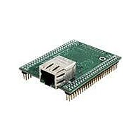
MOD5234-100IR
Manufacturer Part Number
MOD5234-100IR
Description
MOD5234 10/100 ETHERNET MODULE
Manufacturer
NetBurner Inc
Type
Controllers & Processorsr
Datasheets
1.MOD5272-100IR.pdf
(3 pages)
2.MOD5234-100IR.pdf
(4 pages)
3.MOD5234-100IR.pdf
(754 pages)
Specifications of MOD5234-100IR
Interface
I²C, SPI, UART
Voltage - Supply
2.5V
Mounting Type
Surface Mount
Package / Case
Module
Product
Modules
Lead Free Status / RoHS Status
Lead free / RoHS Compliant
Data Format
-
Baud Rates
-
Lead Free Status / Rohs Status
Lead free / RoHS Compliant
Other names
Q4483564


The move-to-SR, STLDSR, and RTE instructions include an optional PST = 0x3 value, indicating
an entry into user mode. Additionally, if the execution of a RTE instruction returns the processor
to emulator mode, a multiple-cycle status of 0xD is signaled.
Similar to the exception processing mode, the stopped state (PST = 0xE) and the halted state
(PST = 0xF) display this status throughout the entire time the ColdFire processor is in the given
mode.
32.8
The hardware in the ColdFire and eTPU debug modules can be configured to allow debug events
to breakpoint either the ColdFire core or the eTPU engine. In order for the eTPU engine to
breakpoint as a result of a cross-triggered ColdFire debug event, or as a result of the assertion of
the BKPT pin input, the appropriate bits in the XCSR and DC registers must be enabled:
XCSR[ETPBKPT], DC[CBI, DBE]. To allow a cross-triggered eTPU engine debug event to
breakpoint the ColdFire core, XCSR[23] and DC[EBC, DBE] must be asserted. The ColdFire
breakpoint hardware is discussed in more detail in
eTPU debug module is discussed in
The inter-debug and cross triggering capabilities controlled by the upper 24 bits of the Extended
Configuration/Status Register (XCSR) see
Register
An example of cross-triggering using the eTPU engine to breakpoint the ColdFire core when
XCSR[23]=1'b1 will breakpoint the ColdFire core on an eTPU engine breakpoint event controlled
in the EDM DCR. The ColdFire core conditions CORE_IS_HALTED and the assertion of the
breakpoint signal to the ColdFire core can be used to breakpoint the eTPU engine using the
XCSR[17:16] bits. Control mechanisms to resume operations between the two processors.
Freescale Semiconductor
Table 32-25. PST/DDATA Specification for Supervisor-Mode Instructions (Continued)
1. Debug Status - Status fields that indicated the state of the eTPU engine halted or not-halted.
2. ColdFire and eTPU Cross-Triggered Breakpoint Conditions - Independent fields for
specifying control of debug events which breakpoint the ColdFire core based on
conditions within the eTPU engine, and events within the ColdFire core that will
breakpoint the eTPU engine.
Instruction
wdebug
stldsr.w
(XCSR)", for details on this register. This functionality can be classified into two groups:
stop
Inter-debug and Cross-Triggering Support
rte
Operand Syntax
<ea>y
#imm
#imm
PST = 0x7, {PST = 0xB, DD = source operand}, {PST = 3}, { PST =0xB,
DD =source operand},
PST = 0x5, {[PST = 0x9AB], DD = target address}
PST = 0x1, {PST = 0xA, DD = destination operand, PST = 0x3}
PST = 0x1,
PST = 0xE
PST = 0x1, {PST = 0xB, DD = source, PST = 0xB, DD = source}
MCF5235 Reference Manual, Rev. 2
Section 32.10, “eTPU Debug Programming
Section 32.4.5, “Extended Configuration/Status
Section 32.6.1, “Theory of
PST/DDATA
Inter-debug and Cross-Triggering Support
Operation", and the
Model."
32-49
Related parts for MOD5234-100IR
Image
Part Number
Description
Manufacturer
Datasheet
Request
R

Part Number:
Description:
MCU, MPU & DSP Development Tools MOD5234 MODULE
Manufacturer:
NetBurner Inc
Datasheet:

Part Number:
Description:
MCU, MPU & DSP Development Tools MOD5234 Core Module Development Kit
Manufacturer:
NetBurner Inc
Datasheet:

Part Number:
Description:
BOARD SERIAL-ETHERNET 512K FLASH
Manufacturer:
NetBurner Inc
Datasheet:

Part Number:
Description:
PROCESSOR MODULE FLASH MOD5272
Manufacturer:
NetBurner Inc
Datasheet:

Part Number:
Description:
PROCESSOR MODULE 512KB FLASH
Manufacturer:
NetBurner Inc
Datasheet:

Part Number:
Description:
DUAL PORT SERIAL-ETHERNET
Manufacturer:
NetBurner Inc
Datasheet:

Part Number:
Description:
PROCESSOR MODULE FLASH
Manufacturer:
NetBurner Inc
Datasheet:

Part Number:
Description:
PROCESSOR MODULE 512KB FLASH
Manufacturer:
NetBurner Inc
Datasheet:

Part Number:
Description:
KIT DEVELOP NETWORK FOR MOD5282
Manufacturer:
NetBurner Inc
Datasheet:

Part Number:
Description:
KIT DEVELOP NETWORK FOR MOD5272
Manufacturer:
NetBurner Inc
Datasheet:

Part Number:
Description:
DUAL PORT SERIAL-ETHERNET
Manufacturer:
NetBurner Inc
Datasheet:

Part Number:
Description:
Ethernet Modules & Development Tools 32 Bit 66MHz 40 Pin DIP Industrial Temp
Manufacturer:
NetBurner Inc
Datasheet:

Part Number:
Description:
Ethernet ICs 32bit 147MHz CAN-to- Ethnt Device IndTemp
Manufacturer:
NetBurner Inc
Datasheet: