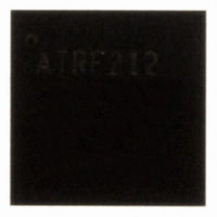
AT86RF212-ZU Atmel, AT86RF212-ZU Datasheet - Page 10

AT86RF212-ZU
Manufacturer Part Number
AT86RF212-ZU
Description
IC TXRX ZIGBE/802.15.4/ISM 32QFN
Manufacturer
Atmel
Datasheet
1.AT86RF212-ZU.pdf
(172 pages)
Specifications of AT86RF212-ZU
Frequency
700MHz, 800MHz, 900MHz
Data Rate - Maximum
250kbps
Modulation Or Protocol
802.15.4 Zigbee, 6LoWPAN, ISM
Applications
ISM, ZigBee™
Power - Output
10dBm
Sensitivity
-110dBm
Voltage - Supply
1.8 V ~ 3.6 V
Current - Receiving
9.2mA
Current - Transmitting
25mA
Data Interface
PCB, Surface Mount
Antenna Connector
PCB, Surface Mount
Operating Temperature
-40°C ~ 85°C
Package / Case
32-VQFN Exposed Pad, 32-HVQFN, 32-SQFN, 32-DHVQFN
Number Of Receivers
1
Number Of Transmitters
1
Wireless Frequency
769 MHz to 935 MHz
Interface Type
SPI
Noise Figure
7 dB
Output Power
21 dB
Operating Supply Voltage
1.8 V, 3 V
Maximum Operating Temperature
+ 85 C
Mounting Style
SMD/SMT
Maximum Supply Current
25 mA
Minimum Operating Temperature
- 40 C
Modulation
OQPSK
Protocol Supported
802.15.4
Operating Temperature (min)
-40C
Operating Temperature (max)
85C
Operating Temperature Classification
Industrial
Lead Free Status / RoHS Status
Lead free / RoHS Compliant
Memory Size
-
Lead Free Status / Rohs Status
Lead free / RoHS Compliant
Available stocks
Company
Part Number
Manufacturer
Quantity
Price
Company:
Part Number:
AT86RF212-ZU
Manufacturer:
HITTITE
Quantity:
5 000
Part Number:
AT86RF212-ZU
Manufacturer:
ATMEL/爱特梅尔
Quantity:
20 000
Part Number:
AT86RF212-ZUR
Manufacturer:
MICROCHIP/微芯
Quantity:
20 000
3 Application Schematic
3.1 Basic Application Schematic
Figure 3-1. Basic Application Schematic
RF
10
AT86RF212
F1
B1
C1
C2
A basic application schematic of the AT86RF212 with a single-ended RF connector is
shown in Figure 3-1. The 50 Ω single-ended RF input is transformed to the 100 Ω
differential RF port impedance using balun B1. The capacitors C1 and C2 provide AC
coupling of the RF input to the RF port. Regulatory rules like FCC 47 CFR section
15.247 [4], ETSI EN 300 220-1 [5], and ERC/REC 70-03 [6] may require an external
filter F1, depending on used transmit power levels.
The power supply bypass capacitors (CB2, CB4) are connected to the external analog
supply pin (EVDD, pin 28) and external digital supply pin (DEVDD, pin 15). Capacitors
CB1 and CB3 are bypass capacitors for the integrated analog and digital voltage
regulators to ensure stable operation. All bypass capacitors should be placed as close
1
2
3
4
5
6
8
7
DIG3
DIG4
AVSS
RFP
RFN
AVSS
DVSS
/RST
32
9
31
10 11 12 13 14 15 16
V
DD
30
CB1
AT86RF212
CB2
29
28
CX1
CB3
27
26
XTAL
CB4
25
CLKM
DVSS
DVSS
SCLK
MOSI
MISO
/SEL
IRQ
CX2
24
23
20
19
22
21
18
17
8168C-MCU Wireless-02/10
C3
R1


