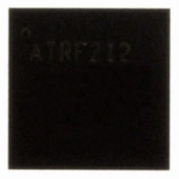
AT86RF212-ZU Atmel, AT86RF212-ZU Datasheet - Page 24

AT86RF212-ZU
Manufacturer Part Number
AT86RF212-ZU
Description
IC TXRX ZIGBE/802.15.4/ISM 32QFN
Manufacturer
Atmel
Datasheet
1.AT86RF212-ZU.pdf
(172 pages)
Specifications of AT86RF212-ZU
Frequency
700MHz, 800MHz, 900MHz
Data Rate - Maximum
250kbps
Modulation Or Protocol
802.15.4 Zigbee, 6LoWPAN, ISM
Applications
ISM, ZigBee™
Power - Output
10dBm
Sensitivity
-110dBm
Voltage - Supply
1.8 V ~ 3.6 V
Current - Receiving
9.2mA
Current - Transmitting
25mA
Data Interface
PCB, Surface Mount
Antenna Connector
PCB, Surface Mount
Operating Temperature
-40°C ~ 85°C
Package / Case
32-VQFN Exposed Pad, 32-HVQFN, 32-SQFN, 32-DHVQFN
Number Of Receivers
1
Number Of Transmitters
1
Wireless Frequency
769 MHz to 935 MHz
Interface Type
SPI
Noise Figure
7 dB
Output Power
21 dB
Operating Supply Voltage
1.8 V, 3 V
Maximum Operating Temperature
+ 85 C
Mounting Style
SMD/SMT
Maximum Supply Current
25 mA
Minimum Operating Temperature
- 40 C
Modulation
OQPSK
Protocol Supported
802.15.4
Operating Temperature (min)
-40C
Operating Temperature (max)
85C
Operating Temperature Classification
Industrial
Lead Free Status / RoHS Status
Lead free / RoHS Compliant
Memory Size
-
Lead Free Status / Rohs Status
Lead free / RoHS Compliant
Available stocks
Company
Part Number
Manufacturer
Quantity
Price
Company:
Part Number:
AT86RF212-ZU
Manufacturer:
HITTITE
Quantity:
5 000
Part Number:
AT86RF212-ZU
Manufacturer:
ATMEL/爱特梅尔
Quantity:
20 000
Part Number:
AT86RF212-ZUR
Manufacturer:
MICROCHIP/微芯
Quantity:
20 000
SLEEP state
The SLEEP state is used when radio transceiver functionality is not required, and thus
the AT86RF212 can be powered down to reduce the overall power consumption.
A power-down scenario is shown in Figure 4-15. When the radio transceiver is in
TRX_OFF state, the microcontroller forces the AT86RF212 to SLEEP by setting
SLP_TR = H. If pin 17 (CLKM) provides a clock to the microcontroller, this clock is
switched off after 35 clock cycles. This enables a microcontroller in a synchronous
system to complete its power-down routine and prevent deadlock situations. The
AT86RF212 awakes when the microcontroller releases pin SLP_TR. This concept
provides the lowest possible power consumption.
The CLKM clock frequency settings for CLKM_CTRL values 6 and 7 are not intended to
directly clock the microcontroller. When using these clock rates, CLKM is turned off
immediately when entering SLEEP state.
Figure 4-15. Sleep and Wake-up Initiated by Asynchronous Microcontroller Timer
Note:
Timing figure t
refers to Table 5-1.
TR2
RX_ON and RX_AACK_ON states
For synchronous systems where CLKM is used as a microcontroller clock source and
the SPI master clock (SCLK) is directly derived from CLKM, the AT86RF212 supports
an additional power-down mode for receive operating states (RX_ON and
RX_AACK_ON).
If an incoming frame is expected and no other applications are running on the
microcontroller, it can be powered down without missing incoming frames. This can be
achieved by a rising edge on pin SLP_TR that turns CLKM off. Then the radio
transceiver state changes from RX_ON or RX_AACK_ON (Extended Operating Mode)
to RX_ON_NOCLK or RX_AACK_ON_NOCLK, respectively. In case that a frame is
received (e.g. indicated by an IRQ_2 (RX_START) interrupt), the clock output CLKM is
automatically switched on again. This scenario is shown in Figure 4-16. In RX_ON
state, the clock at pin 17 (CLKM) is switched off after 35 clock cycles when setting the
pin SLP_TR = H.
The CLKM clock frequency settings for CLKM_CTRL values 6 and 7 are not intended to
directly clock the microcontroller. When using these clock rates, CLKM is turned off
immediately when entering RX_ON_NOCLK or RX_AACK_ON_NOCLK.
In states RX_(AACK)_ON_NOCLK and RX_(AACK)_ON, the radio transceiver current
consumptions
are equivalent.
However,
the RX_(AACK)_ON_NOCLK current
consumption is reduced by the current required for driving pin 17 (CLKM).
AT86RF212
24
8168C-MCU Wireless-02/10


