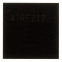
AT86RF212-ZU Atmel, AT86RF212-ZU Datasheet - Page 151

AT86RF212-ZU
Manufacturer Part Number
AT86RF212-ZU
Description
IC TXRX ZIGBE/802.15.4/ISM 32QFN
Manufacturer
Atmel
Datasheet
1.AT86RF212-ZU.pdf
(172 pages)
Specifications of AT86RF212-ZU
Frequency
700MHz, 800MHz, 900MHz
Data Rate - Maximum
250kbps
Modulation Or Protocol
802.15.4 Zigbee, 6LoWPAN, ISM
Applications
ISM, ZigBee™
Power - Output
10dBm
Sensitivity
-110dBm
Voltage - Supply
1.8 V ~ 3.6 V
Current - Receiving
9.2mA
Current - Transmitting
25mA
Data Interface
PCB, Surface Mount
Antenna Connector
PCB, Surface Mount
Operating Temperature
-40°C ~ 85°C
Package / Case
32-VQFN Exposed Pad, 32-HVQFN, 32-SQFN, 32-DHVQFN
Number Of Receivers
1
Number Of Transmitters
1
Wireless Frequency
769 MHz to 935 MHz
Interface Type
SPI
Noise Figure
7 dB
Output Power
21 dB
Operating Supply Voltage
1.8 V, 3 V
Maximum Operating Temperature
+ 85 C
Mounting Style
SMD/SMT
Maximum Supply Current
25 mA
Minimum Operating Temperature
- 40 C
Modulation
OQPSK
Protocol Supported
802.15.4
Operating Temperature (min)
-40C
Operating Temperature (max)
85C
Operating Temperature Classification
Industrial
Lead Free Status / RoHS Status
Lead free / RoHS Compliant
Memory Size
-
Lead Free Status / Rohs Status
Lead free / RoHS Compliant
Available stocks
Company
Part Number
Manufacturer
Quantity
Price
Company:
Part Number:
AT86RF212-ZU
Manufacturer:
HITTITE
Quantity:
5 000
Part Number:
AT86RF212-ZU
Manufacturer:
ATMEL/爱特梅尔
Quantity:
20 000
Part Number:
AT86RF212-ZUR
Manufacturer:
MICROCHIP/微芯
Quantity:
20 000
10.4 Digital Interface Timing Characteristics
8168C-MCU Wireless-02/10
No.
10.4.1
10.4.2
10.4.3
10.4.4
10.4.5
10.4.6
10.4.7
10.4.8
10.4.9
10.4.10
10.4.11
10.4.12
10.4.13
10.4.14
10.4.15
10.4.16
10.4.17
Symbol
f
f
t
t
t
t
t
t
t
t
t
t
t
t
t
f
t
sync
async
1
2
3
4
5
6
7
8
9
10
11
12
13
CLKM
IRQ
Parameter
SCLK frequency
SCLK frequency
/SEL falling edge to MISO active
SCLK falling edge to MISO out
MOSI setup time
MOSI hold time
LSB last byte to MSB next byte
/SEL rising edge to MISO tri state
SLP_TR pulse width
SPI idle time between
consecutive SPI accesses:
SEL rising to falling edge
SCLK rising edge LSB to /SEL
rising edge
Reset pulse width
SPI access latency after reset
AES core cycle time
Dynamic frame buffer protection:
IRQ latency
Clock frequency at pin 17
(CLKM)
IRQ_2, IRQ_3, IRQ_4 latency
Test Conditions: T
Note:
1. The capacitive load should not be larger than 50 pF for all I/Os when using the
default driver strength settings, refer to section 2.2.2.1. Generally, large load
capacitances increase the overall current consumption.
Condition
Synchronous operation
Asynchronous operation
Data hold time
SPI read/write, standard SRAM
and frame access modes
Fast SRAM read/write access
mode, refer to section 9.1.5
TX start trigger
SPI read/write, standard SRAM
and frame access modes
Fast SRAM read/write access
mode, refer to section 9.1.5
≥ 10 clock cycles at 16 MHz
≥ 10 clock cycles at 16 MHz
Programmable via
register 0x03 (TRX_CTRL_0)
Relative to the event to be
indicated
OP
= 25 °C, V
DD
= 3.0 V, C
L
= 50 pF
250
500
250
500
25
10
10
Min.
62.5
625
625
(7)
(7)
(7)
(8)
(8)
(8)
(8)
1/50
1/25
1/40
1/16
250
1/4
16
Typ.
750
0
1
2
4
8
9
24
(2)
(2)
(2)
(2)
(2)
(9)
(2)
(2)
(8)
(3)
(4)
(5)
(6)
AT86RF212
Note
180
Max.
10
7.5
8
(8)
(7)
(1)
Units
MHz
MHz
MHz
MHz
MHz
MHz
MHz
MHz
MHz
MHz
MHz
MHz
MHz
ns
ns
ns
ns
ns
ns
ns
ns
ns
ns
ns
ns
ns
µs
ns
µs
151


