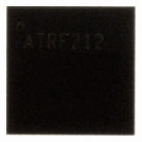
AT86RF212-ZU Atmel, AT86RF212-ZU Datasheet - Page 78

AT86RF212-ZU
Manufacturer Part Number
AT86RF212-ZU
Description
IC TXRX ZIGBE/802.15.4/ISM 32QFN
Manufacturer
Atmel
Datasheet
1.AT86RF212-ZU.pdf
(172 pages)
Specifications of AT86RF212-ZU
Frequency
700MHz, 800MHz, 900MHz
Data Rate - Maximum
250kbps
Modulation Or Protocol
802.15.4 Zigbee, 6LoWPAN, ISM
Applications
ISM, ZigBee™
Power - Output
10dBm
Sensitivity
-110dBm
Voltage - Supply
1.8 V ~ 3.6 V
Current - Receiving
9.2mA
Current - Transmitting
25mA
Data Interface
PCB, Surface Mount
Antenna Connector
PCB, Surface Mount
Operating Temperature
-40°C ~ 85°C
Package / Case
32-VQFN Exposed Pad, 32-HVQFN, 32-SQFN, 32-DHVQFN
Number Of Receivers
1
Number Of Transmitters
1
Wireless Frequency
769 MHz to 935 MHz
Interface Type
SPI
Noise Figure
7 dB
Output Power
21 dB
Operating Supply Voltage
1.8 V, 3 V
Maximum Operating Temperature
+ 85 C
Mounting Style
SMD/SMT
Maximum Supply Current
25 mA
Minimum Operating Temperature
- 40 C
Modulation
OQPSK
Protocol Supported
802.15.4
Operating Temperature (min)
-40C
Operating Temperature (max)
85C
Operating Temperature Classification
Industrial
Lead Free Status / RoHS Status
Lead free / RoHS Compliant
Memory Size
-
Lead Free Status / Rohs Status
Lead free / RoHS Compliant
Available stocks
Company
Part Number
Manufacturer
Quantity
Price
Company:
Part Number:
AT86RF212-ZU
Manufacturer:
HITTITE
Quantity:
5 000
Part Number:
AT86RF212-ZU
Manufacturer:
ATMEL/爱特梅尔
Quantity:
20 000
Part Number:
AT86RF212-ZUR
Manufacturer:
MICROCHIP/微芯
Quantity:
20 000
6.3.3 Automatic FCS Generation
6.3.4 Automatic FCS Check
6.3.5 Register Description
78
AT86RF212
be the polynomial representing the sequence of bits for which the checksum is to be
computed. Multiply M(x) by
Divide
polynomial
The FCS field is given by the coefficients of the remainder polynomial
Example:
Considering a 5-octet ACK frame, the MHR field consists of
The leftmost bit (b
The leftmost bit (r
The automatic FCS generation is enabled with register bit TX_AUTO_CRC_ON = 1.
This allows the AT86RF212 to compute the FCS autonomously. For a frame with a
frame length field specified as N (3 ≤ N ≤ 127), the FCS is calculated on the first N-2
octets in the Frame Buffer and the resulting FCS octets are transmitted in place of the
last two octets of the Frame Buffer.
Basic and Extended Operating Modes are provided with an automatic FCS check for
received frames. Register bit RX_CRC_VALID (register 0x06, PHY_RSSI) is set to 1 if
the FCS of a received frame is valid. In addition, bit 7 of byte RX_STATUS is set
accordingly, refer to section 4.3.2.
In Extended Operating Mode, the RX_AACK procedure does not accept a frame if the
corresponding FCS is not valid, i.e. no TRX_END interrupt is issued. When operating in
TX_ARET mode, the FCS of a received ACK is automatically checked. If it is not
correct, the ACK is not accepted; refer to section 5.2.4 for automated retries.
Register 0x04 (TRX_CTRL_1):
The TRX_CTRL_1 register is a multi-purpose register to control various operating
modes and settings of the radio transceiver, see Table 6-22.
Table 6-22. Register 0x04 (TRX_CTRL_1)
Bit
Name
Read/Write
Reset Value
Bit
Name
Read/Write
Reset Value
N
0100 0000 0000 0000 0101 0110 .
0010 0111 1001 1110 .
R
N
(x
(
(
x
)
x
)
)
modulo 2 by the generator polynomial
7
PA_EXT_EN
R/W
0
3
SPI_CMD_MODE
R/W
0
=
=
M
r
0
0
0
) is transmitted first in time.
) is transmitted first in time. The FCS would be
x
(
15
x
)
+
⋅
x
x r
16
1
14
x
.
16
+
, giving the polynomial
...
6
IRQ_2_EXT_EN
R/W
0
2
SPI_CMD_MODE
R/W
0
+
r
14
x
+
r
15
5
TX_AUTO_CRC_ON
R/W
1
1
IRQ_MASK_MODE
R/W
0
G
16
(
x
)
to obtain the remainder
8168C-MCU Wireless-02/10
4
RX_BL_CTRL
R/W
0
0
IRQ_POLARITY
R/W
0
R
(x
)
.


