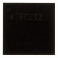
AT86RF212-ZU Atmel, AT86RF212-ZU Datasheet - Page 93

AT86RF212-ZU
Manufacturer Part Number
AT86RF212-ZU
Description
IC TXRX ZIGBE/802.15.4/ISM 32QFN
Manufacturer
Atmel
Datasheet
1.AT86RF212-ZU.pdf
(172 pages)
Specifications of AT86RF212-ZU
Frequency
700MHz, 800MHz, 900MHz
Data Rate - Maximum
250kbps
Modulation Or Protocol
802.15.4 Zigbee, 6LoWPAN, ISM
Applications
ISM, ZigBee™
Power - Output
10dBm
Sensitivity
-110dBm
Voltage - Supply
1.8 V ~ 3.6 V
Current - Receiving
9.2mA
Current - Transmitting
25mA
Data Interface
PCB, Surface Mount
Antenna Connector
PCB, Surface Mount
Operating Temperature
-40°C ~ 85°C
Package / Case
32-VQFN Exposed Pad, 32-HVQFN, 32-SQFN, 32-DHVQFN
Number Of Receivers
1
Number Of Transmitters
1
Wireless Frequency
769 MHz to 935 MHz
Interface Type
SPI
Noise Figure
7 dB
Output Power
21 dB
Operating Supply Voltage
1.8 V, 3 V
Maximum Operating Temperature
+ 85 C
Mounting Style
SMD/SMT
Maximum Supply Current
25 mA
Minimum Operating Temperature
- 40 C
Modulation
OQPSK
Protocol Supported
802.15.4
Operating Temperature (min)
-40C
Operating Temperature (max)
85C
Operating Temperature Classification
Industrial
Lead Free Status / RoHS Status
Lead free / RoHS Compliant
Memory Size
-
Lead Free Status / Rohs Status
Lead free / RoHS Compliant
Available stocks
Company
Part Number
Manufacturer
Quantity
Price
Company:
Part Number:
AT86RF212-ZU
Manufacturer:
HITTITE
Quantity:
5 000
Part Number:
AT86RF212-ZU
Manufacturer:
ATMEL/爱特梅尔
Quantity:
20 000
Part Number:
AT86RF212-ZUR
Manufacturer:
MICROCHIP/微芯
Quantity:
20 000
7.1.2 Configuration
7.1.3 Symbol Period
7.1.4 Proprietary High Data Rate Modes
7.1.4.1 Overview
7.1.4.2 High Data Rate Frame Structure
8168C-MCU Wireless-02/10
The PHY mode can be selected by setting appropriate register bits of register 0x0C
(TRX_CTRL_2), refer to section 7.1.5. During configuration, the transceiver needs to
be in state TRX_OFF.
Within IEEE 802.15.4 and, accordingly, within this document, time references are often
specified in units of symbol periods, leading to a PHY mode independent description.
Table 7-2 shows the duration of the symbol period. Note that for the proprietary High
Data Rate Modes, the symbol period is (by definition) the same as the symbol period of
the corresponding base mode.
Table 7-2. Duration of the Symbol Period
The main features are:
• High data rates up to 1000 kbit/s
• Support of Basic and Extended Operating Mode
• Reduced ACK timing (optional)
The AT86RF212 supports alternative data rates of {200, 400, 500, 1000} kbit/s for
applications not necessarily targeting IEEE 802.15.4 compliant networks.
The High Data Rate Modes utilize the same RF channel bandwidth as the
IEEE 802.15.4-2006 sub-1 GHz O-QPSK modes. Higher data rates are achieved by
modified O-QPSK spreading codes having reduced code lengths. The lengths are
reduced by the factor 2 or by the factor 4.
For O-QPSK with 400 kchip/s, this leads to a data rate of 200 kbit/s (2-fold) and 400
kbit/s (4-fold), respectively.
For O-QPSK with 1000 kchip/s, the resulting data rate is 500 kbit/s (2-fold) and 1000
kbit/s (4-fold), respectively.
Due to the decreased spreading factor, the sensitivity of the receiver is reduced.
Section 10.7, parameter 10.7.1, shows typical values of the sensitivity for different data
rates. Note that the sensitivity values of the High Data Rate Modes are provided for a
maximum PSDU length of 127 octets.
In order to allow robust frame synchronization, high data rate modulation is restricted to
the PSDU part only. The PPDU header (the preamble, the SFD, and the PHR field) are
transmitted with the IEEE 802.15.4-2006 O-QPSK rate of either 100 kbit/s or 250 kbit/s
(basic rates), see Figure 7-2.
Modulation
BPSK
O-QPSK
PSDU Data Rate
250, 500, 1000
100, 200, 400
[kbit/s]
20
40
Duration of Symbol Period
AT86RF212
[µs]
50
25
40
16
93


