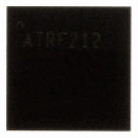
AT86RF212-ZU Atmel, AT86RF212-ZU Datasheet - Page 25

AT86RF212-ZU
Manufacturer Part Number
AT86RF212-ZU
Description
IC TXRX ZIGBE/802.15.4/ISM 32QFN
Manufacturer
Atmel
Datasheet
1.AT86RF212-ZU.pdf
(172 pages)
Specifications of AT86RF212-ZU
Frequency
700MHz, 800MHz, 900MHz
Data Rate - Maximum
250kbps
Modulation Or Protocol
802.15.4 Zigbee, 6LoWPAN, ISM
Applications
ISM, ZigBee™
Power - Output
10dBm
Sensitivity
-110dBm
Voltage - Supply
1.8 V ~ 3.6 V
Current - Receiving
9.2mA
Current - Transmitting
25mA
Data Interface
PCB, Surface Mount
Antenna Connector
PCB, Surface Mount
Operating Temperature
-40°C ~ 85°C
Package / Case
32-VQFN Exposed Pad, 32-HVQFN, 32-SQFN, 32-DHVQFN
Number Of Receivers
1
Number Of Transmitters
1
Wireless Frequency
769 MHz to 935 MHz
Interface Type
SPI
Noise Figure
7 dB
Output Power
21 dB
Operating Supply Voltage
1.8 V, 3 V
Maximum Operating Temperature
+ 85 C
Mounting Style
SMD/SMT
Maximum Supply Current
25 mA
Minimum Operating Temperature
- 40 C
Modulation
OQPSK
Protocol Supported
802.15.4
Operating Temperature (min)
-40C
Operating Temperature (max)
85C
Operating Temperature Classification
Industrial
Lead Free Status / RoHS Status
Lead free / RoHS Compliant
Memory Size
-
Lead Free Status / Rohs Status
Lead free / RoHS Compliant
Available stocks
Company
Part Number
Manufacturer
Quantity
Price
Company:
Part Number:
AT86RF212-ZU
Manufacturer:
HITTITE
Quantity:
5 000
Part Number:
AT86RF212-ZU
Manufacturer:
ATMEL/爱特梅尔
Quantity:
20 000
Part Number:
AT86RF212-ZUR
Manufacturer:
MICROCHIP/微芯
Quantity:
20 000
Figure 4-16. Wake-Up Initiated by Radio Transceiver Interrupt
4.7 Interrupt Logic
4.7.1 Overview
Table 4-15. Interrupt Description in Basic Operating Mode
8168C-MCU Wireless-02/10
IRQ Name
IRQ_7 (BAT_LOW)
IRQ_6 (TRX_UR)
IRQ_5 (AMI)
IRQ_4 (CCA_ED_DONE)
IRQ_3 (TRX_END)
IRQ_2 (RX_START)
IRQ_1 (PLL_UNLOCK)
IRQ_0 (PLL_LOCK)
Description
Indicates a supply voltage below the programmed threshold
Indicates a Frame Buffer access violation
Indicates address matching
Multi-functional interrupt:
1. AWAKE_END:
2. CCA_ED_DONE:
RX: Indicates the completion of a frame reception
TX: Indicates the completion of a frame transmission
Indicates the start of a PSDU reception; the TRX state changes to BUSY_RX;
the PHR is valid to be read from Frame Buffer.
Indicates PLL unlock; if the radio transceiver is in BUSY_TX / BUSY_TX_ARET state,
the PA is turned off immediately.
Indicates PLL lock
•
•
The AT86RF212 supports 8 interrupt requests as listed in Table 4-15. Each interrupt is
enabled by setting the corresponding bit in the interrupt mask register 0x0E
(IRQ_MASK). Internally, each pending interrupt is stored in a separate bit of the
interrupt status register. All interrupt events are OR-combined to a single external
interrupt signal (IRQ, pin 24). If an interrupt is issued (pin IRQ = H), the microcontroller
shall read the interrupt status register 0x0F (IRQ_STATUS) to determine the source of
the interrupt. A read access to this register clears the interrupt status register and thus
the IRQ pin, too.
Interrupts are not cleared automatically when the event that caused them vanishes.
Exceptions
occurrence of one clears the other.
The supported interrupts for the Basic Operating Mode are summarized in Table 4-15.
Indicates radio transceiver reached TRX_OFF state at the end of P_ON
TRX_OFF and SLEEP
Indicates the end of a CCA or ED measurement
are
IRQ_0 (PLL_LOCK)
TRX_OFF state transition
and
IRQ_1 (PLL_UNLOCK)
AT86RF212
because
Section
5.1.2.3
7.6.4
7.4.3
6.6.4
5.1.3
5.1.3
7.8.5
7.8.5
6.2
the
25
o


