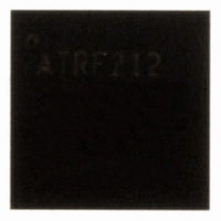
AT86RF212-ZU Atmel, AT86RF212-ZU Datasheet - Page 109

AT86RF212-ZU
Manufacturer Part Number
AT86RF212-ZU
Description
IC TXRX ZIGBE/802.15.4/ISM 32QFN
Manufacturer
Atmel
Datasheet
1.AT86RF212-ZU.pdf
(172 pages)
Specifications of AT86RF212-ZU
Frequency
700MHz, 800MHz, 900MHz
Data Rate - Maximum
250kbps
Modulation Or Protocol
802.15.4 Zigbee, 6LoWPAN, ISM
Applications
ISM, ZigBee™
Power - Output
10dBm
Sensitivity
-110dBm
Voltage - Supply
1.8 V ~ 3.6 V
Current - Receiving
9.2mA
Current - Transmitting
25mA
Data Interface
PCB, Surface Mount
Antenna Connector
PCB, Surface Mount
Operating Temperature
-40°C ~ 85°C
Package / Case
32-VQFN Exposed Pad, 32-HVQFN, 32-SQFN, 32-DHVQFN
Number Of Receivers
1
Number Of Transmitters
1
Wireless Frequency
769 MHz to 935 MHz
Interface Type
SPI
Noise Figure
7 dB
Output Power
21 dB
Operating Supply Voltage
1.8 V, 3 V
Maximum Operating Temperature
+ 85 C
Mounting Style
SMD/SMT
Maximum Supply Current
25 mA
Minimum Operating Temperature
- 40 C
Modulation
OQPSK
Protocol Supported
802.15.4
Operating Temperature (min)
-40C
Operating Temperature (max)
85C
Operating Temperature Classification
Industrial
Lead Free Status / RoHS Status
Lead free / RoHS Compliant
Memory Size
-
Lead Free Status / Rohs Status
Lead free / RoHS Compliant
Available stocks
Company
Part Number
Manufacturer
Quantity
Price
Company:
Part Number:
AT86RF212-ZU
Manufacturer:
HITTITE
Quantity:
5 000
Part Number:
AT86RF212-ZU
Manufacturer:
ATMEL/爱特梅尔
Quantity:
20 000
Part Number:
AT86RF212-ZUR
Manufacturer:
MICROCHIP/微芯
Quantity:
20 000
7.4 Frame Buffer
7.4.1 Data Management
8168C-MCU Wireless-02/10
The map EU1 takes more supply current than the North American map and uses the
normal (linearized) PA mode to provide medium output power up to -1 dBm for
O-QPSK-SIN-RC-{100/200/400} modes and 4 dBm for BPSK-20 mode.
The map EU2 uses the boost mode to provide higher TX power levels at the expense of
higher supply current. As a result, the maximum TX power is 2 dBm for O-QPSK-SIN-
RC-{100/200/400} and 5 dBm for BPSK-20.
Due to great regional distinctions of regulatory requirements, it is not possible to cover
all restrictions in this data sheet. Manufactures must take the responsibility to check
measurement results against the latest regulations of nations into which they market.
The AT86RF212 contains a 128 byte dual port SRAM. One port is connected to the SPI
interface, the other one to the internal transmitter and receiver modules. For data
communication, both ports are independent and simultaneously accessible.
The Frame Buffer utilizes the SRAM address space 0x00 to 0x7F for RX and TX
operation of the radio transceiver and can keep a single IEEE 802.15.4 RX or a single
TX frame of maximum length at a time.
Frame Buffer access modes are described in section 4.3.2. Frame Buffer access
conflicts are indicated by an underrun interrupt IRQ_6 (TRX_UR). Note that this
interrupt also occurs on the attempt to write frames longer than 127 octets to the Frame
Buffer (overflow). In this case, the content of the Frame Buffer is undefined.
Frame Buffer access is only possible if the digital voltage regulator is turned on. This is
valid in all device states except in SLEEP state. An access in P_ON state is possible
once pin 17 (CLKM) provides the 1 MHz master clock.
Data in Frame Buffer (received data or data to be transmitted) can be changed by:
• Frame Buffer or SRAM write access over SPI
• receiving a new frame in BUSY_RX or BUSY_RX_AACK state
• a change into SLEEP state
• a reset
By default, there is no protection of the Frame Buffer against overwriting. Therefore, if a
frame is received during Frame Buffer read access of a previously received frame,
interrupt IRQ_6 (TRX_UR) is issued and the stored data might be overwritten.
Even so, the old frame data can be read if the SPI data rate is higher than the effective
over air data rate. For a data rate of 250 kbit/s, a minimum SPI clock rate of 1 MHz is
recommended. Finally, the microcontroller should check the transferred frame data
integrity by an FCS check.
To protect the Frame Buffer content against being overwritten by newly incoming
frames, the radio transceiver state should be changed to PLL_ON state after reception.
This can be achieved by writing the command PLL_ON to register bits TRX_CMD
(register 0x02, TRX_STATE) while or immediately after receiving the frame.
Alternatively, Dynamic Frame Buffer Protection can be used to protect received frames
against overwriting; for details, refer to section 9.7. Both procedures do not protect the
Frame Buffer from overwriting by the microcontroller.
AT86RF212
109


