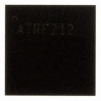
AT86RF212-ZU Atmel, AT86RF212-ZU Datasheet - Page 36

AT86RF212-ZU
Manufacturer Part Number
AT86RF212-ZU
Description
IC TXRX ZIGBE/802.15.4/ISM 32QFN
Manufacturer
Atmel
Datasheet
1.AT86RF212-ZU.pdf
(172 pages)
Specifications of AT86RF212-ZU
Frequency
700MHz, 800MHz, 900MHz
Data Rate - Maximum
250kbps
Modulation Or Protocol
802.15.4 Zigbee, 6LoWPAN, ISM
Applications
ISM, ZigBee™
Power - Output
10dBm
Sensitivity
-110dBm
Voltage - Supply
1.8 V ~ 3.6 V
Current - Receiving
9.2mA
Current - Transmitting
25mA
Data Interface
PCB, Surface Mount
Antenna Connector
PCB, Surface Mount
Operating Temperature
-40°C ~ 85°C
Package / Case
32-VQFN Exposed Pad, 32-HVQFN, 32-SQFN, 32-DHVQFN
Number Of Receivers
1
Number Of Transmitters
1
Wireless Frequency
769 MHz to 935 MHz
Interface Type
SPI
Noise Figure
7 dB
Output Power
21 dB
Operating Supply Voltage
1.8 V, 3 V
Maximum Operating Temperature
+ 85 C
Mounting Style
SMD/SMT
Maximum Supply Current
25 mA
Minimum Operating Temperature
- 40 C
Modulation
OQPSK
Protocol Supported
802.15.4
Operating Temperature (min)
-40C
Operating Temperature (max)
85C
Operating Temperature Classification
Industrial
Lead Free Status / RoHS Status
Lead free / RoHS Compliant
Memory Size
-
Lead Free Status / Rohs Status
Lead free / RoHS Compliant
Available stocks
Company
Part Number
Manufacturer
Quantity
Price
Company:
Part Number:
AT86RF212-ZU
Manufacturer:
HITTITE
Quantity:
5 000
Part Number:
AT86RF212-ZU
Manufacturer:
ATMEL/爱特梅尔
Quantity:
20 000
Part Number:
AT86RF212-ZUR
Manufacturer:
MICROCHIP/微芯
Quantity:
20 000
5.1.4.1 Power-on Procedure
5.1.4.2 Wake-up Procedure
5.1.4.3 State Change from TRX_OFF to PLL_ON / RX_ON
36
AT86RF212
The power-on procedure to P_ON state is shown in Figure 5-3.
Figure 5-3. Power-on Procedure to P_ON State
When the external supply voltage (V
transceiver enables the crystal oscillator (XOSC) and the internal 1.8 V voltage
regulator for the digital domain (DVREG). After t
at pin 17 (CLKM) at a default rate of 1 MHz. If CLKM is available, the SPI has already
been enabled and can be used to control the transceiver. As long as no state change
towards state TRX_OFF is performed, the radio transceiver remains in P_ON state.
The wake-up procedure from SLEEP state is shown in Figure 5-4.
Figure 5-4. Wake-up Procedure from SLEEP State
The radio transceiver’s SLEEP state is left by releasing pin SLP_TR to logic low. This
restarts the XOSC and DVREG. After t
The internal clock signal is available and provided to pin 17 (CLKM) if enabled.
This procedure is similar to power-on, however, the radio transceiver automatically
ends in TRX_OFF state. During this, the filter-tuning network (FTN) calibration is
performed. Entering TRX_OFF state is signaled by IRQ_4 (AWAKE_END) if this
interrupt was enabled by the appropriate mask register bit.
The transition from TRX_OFF to PLL_ON or RX_ON state and further to RX_ON or
PLL_ON is shown in Figure 5-5.
TR2
DD
) is supplied to the AT86RF212, the radio
, the radio transceiver enters TRX_OFF state.
TR1
, the master clock signal is available
8168C-MCU Wireless-02/10


