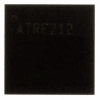
AT86RF212-ZU Atmel, AT86RF212-ZU Datasheet - Page 98

AT86RF212-ZU
Manufacturer Part Number
AT86RF212-ZU
Description
IC TXRX ZIGBE/802.15.4/ISM 32QFN
Manufacturer
Atmel
Datasheet
1.AT86RF212-ZU.pdf
(172 pages)
Specifications of AT86RF212-ZU
Frequency
700MHz, 800MHz, 900MHz
Data Rate - Maximum
250kbps
Modulation Or Protocol
802.15.4 Zigbee, 6LoWPAN, ISM
Applications
ISM, ZigBee™
Power - Output
10dBm
Sensitivity
-110dBm
Voltage - Supply
1.8 V ~ 3.6 V
Current - Receiving
9.2mA
Current - Transmitting
25mA
Data Interface
PCB, Surface Mount
Antenna Connector
PCB, Surface Mount
Operating Temperature
-40°C ~ 85°C
Package / Case
32-VQFN Exposed Pad, 32-HVQFN, 32-SQFN, 32-DHVQFN
Number Of Receivers
1
Number Of Transmitters
1
Wireless Frequency
769 MHz to 935 MHz
Interface Type
SPI
Noise Figure
7 dB
Output Power
21 dB
Operating Supply Voltage
1.8 V, 3 V
Maximum Operating Temperature
+ 85 C
Mounting Style
SMD/SMT
Maximum Supply Current
25 mA
Minimum Operating Temperature
- 40 C
Modulation
OQPSK
Protocol Supported
802.15.4
Operating Temperature (min)
-40C
Operating Temperature (max)
85C
Operating Temperature Classification
Industrial
Lead Free Status / RoHS Status
Lead free / RoHS Compliant
Memory Size
-
Lead Free Status / Rohs Status
Lead free / RoHS Compliant
Available stocks
Company
Part Number
Manufacturer
Quantity
Price
Company:
Part Number:
AT86RF212-ZU
Manufacturer:
HITTITE
Quantity:
5 000
Part Number:
AT86RF212-ZU
Manufacturer:
ATMEL/爱特梅尔
Quantity:
20 000
Part Number:
AT86RF212-ZUR
Manufacturer:
MICROCHIP/微芯
Quantity:
20 000
The BBP performs further filtering and signal processing. In RX_ON state, the receiver
searches for the synchronization header. Once the synchronization is established and
the SFD is found, the received signal is demodulated and provided to the Frame Buffer.
The receiver performs a state change indicated by register bits TRX_STATUS (register
0x01, TRX_STATUS) to BUSY_RX. Once the whole frame is received, the receiver
switches back to RX_ON to listen on the channel. A similar scheme applies to the
Extended Operating Mode.
The receiver is designed to handle reference oscillator accuracies up to ±60 ppm; refer
to section 10.5, parameter 10.5.6. This results in the estimation and correction of
frequency and symbol rate errors up to ±120 ppm.
Several status information are generated during the receive process: LQI, ED, and
RX_STATUS. They are automatically appended during Frame Read Access, refer to
section 4.3.2. Some information is also available through register access, e.g. ED value
(register 0x07, PHY_ED_LEVEL) and FCS correctness (register 0x06, PHY_RSSI).
The Extended Operating Mode of the AT86RF212 supports frame filtering and pending
data indication.
The frame receive procedure, including the radio transceiver setup for reception and
reading PSDU data from the Frame Buffer, is described in section 8.1.
7.2.2 Configuration
In Basic Operating Mode, the receiver is enabled by writing command RX_ON to
register bits TRX_CMD (register 0x02, TRX_STATE) in states TRX_OFF or PLL_ON. In
Extended Operating Mode, the receiver is enabled for RX_AACK operation from state
PLL_ON by writing the command RX_AACK_ON.
There is no additional configuration required to receive IEEE 802.15.4 compliant frames
when using the Basic Operating Mode. However, the frame reception in the Extended
Operating Mode requires further register configurations. For details, refer to section
5.2.2.
For specific applications, the receiver can be configured to handle critical environments,
to simplify the interaction with the microcontroller, or to operate different data rates.
The AT86RF212 receiver has an outstanding sensitivity performance. At certain
conditions (interference floor, High Data Rate Modes, refer to section 7.1.4), it may be
useful to manually decrease this sensitivity. This is achieved by adjusting the
synchronization header detector threshold using register bits RX_PDT_LEVEL (register
0x15, RX_SYN). Received signals with a RSSI value below the threshold do not
activate the demodulation process.
Furthermore, it may be useful to protect a received frame against overwriting by
subsequent received frames. A Dynamic Frame Buffer Protection is enabled with
register bit RX_SAFE_MODE (register 0x0C, TRX_CTRL_2) set, see section 9.7. The
receiver remains in RX_ON or RX_AACK_ON state until the whole frame is uploaded
by the microcontroller, indicated by /SEL = H during the SPI Frame Receive Mode. The
Frame Buffer content is only protected if the FCS is valid.
A Static Frame Buffer Protection is enabled with register bit RX_PDT_DIS (register
0x15, RX_SYN) set. The receiver remains in RX_ON or RX_AACK_ON state and no
further SHR is detected until the register bit RX_PDT_DIS is set back.
AT86RF212
98
8168C-MCU Wireless-02/10


